Start-up and Parameter Settings
FLOWSIC100 · Operating Instructions · 8012513/YSA5/V 2-1/2016-07 · © SICK Engineering GmbH 151
Subject to change without notice
4.3.6 Calibrating flow rate and temperature measurement
This Section describes parameter settings that are necessary for calibrating gas flow rate
and temperature measurements, and for outputting the volume flow in the standard state.
To do this, set the measuring system to “Maintenance” mode and enter the Level 1
password. For input, select type FLOWSIC100 in the "Device Catalog" register, field
"Detected Devices" (
p. 124, Table 3) and then select subdirectory "Installation Parameters".
Entering calibration coefficients for gas flow rate measurement
Enter the calibration coefficients determined with a network point measurement using a
reference system in the group "Calibration coefficients / Calibration coefficients for flow
rate".
Default values from the factory are Cv2 = 0, Cv1 = 1, Cv0 = 0.
Calibrating temperature measurements
The accuracy of the acoustic temperature measurement with the FLOWSIC100 depends
quadratical on the active measuring path and sound velocity of the real gas under
standard conditions (
p. 15, 2.2.3). Exact acoustic temperature measurements are only
possible when the sound velocity of the real gas remains constant at a reference
temperature. Since this is seldom the case, the internal temperature calculation in the
device must be calibrated if it is to be used to scale the volume flow.
To calibrate the measurement, determine the value pairs from separately measured gas
temperature (for example, with PT100 sensor) and display on the LC-Display at a minimum
of two different gas temperatures. Convert the calculated values to absolute temperatures
(add 273.15 K). Then use a regression function to calculate the coefficients (for two pairs
by linear, with more value pairs also by quadratic regression). Enter CT_2, CT_1 and CT_0
in the “Calibration coefficients / Calibration coefficients for temperature” group.
Default settings from the factory are CT_2 = 0, CT_1 = 1, CT_0 = 0.
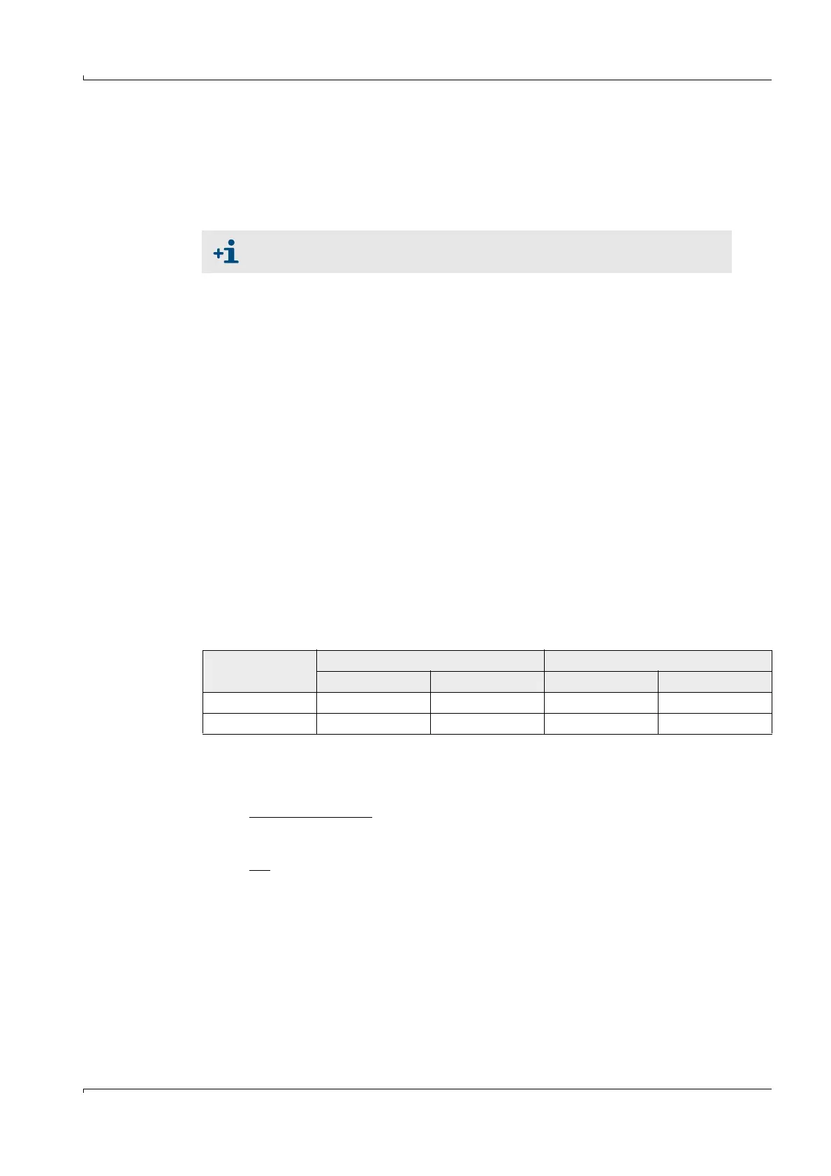
Example:
Refer also to
p. 44, 2.4
Measurement
FLOWSIC display Measured value PT100
T in °C T
absolute
in K T in °C T
absolute
in K
1 128 401 115 388
2 186 459 170 443
T
KAL
=CT_1 • T
FLOWSIC
+ CT_0
CT_1 =
CT_0 =
• (T2
PT100
+ T1
PT100
– CT_1 • (T2
FLOWSIC
+ T1
FLOWSIC
))
CT_1 = 0.9483
CT_0 = 7.7310
T2
PT100
– T1
PT100
T2
FLOWSIC
– T1
FLOWSIC
1
2