50 FLOWSIC100 · Operating Instructions · 8012513/YSA5/V2-1/2016-07 · © SICK Engineering GmbH
Assembly and Installation
Subject to change without notice
3.1 Project planning
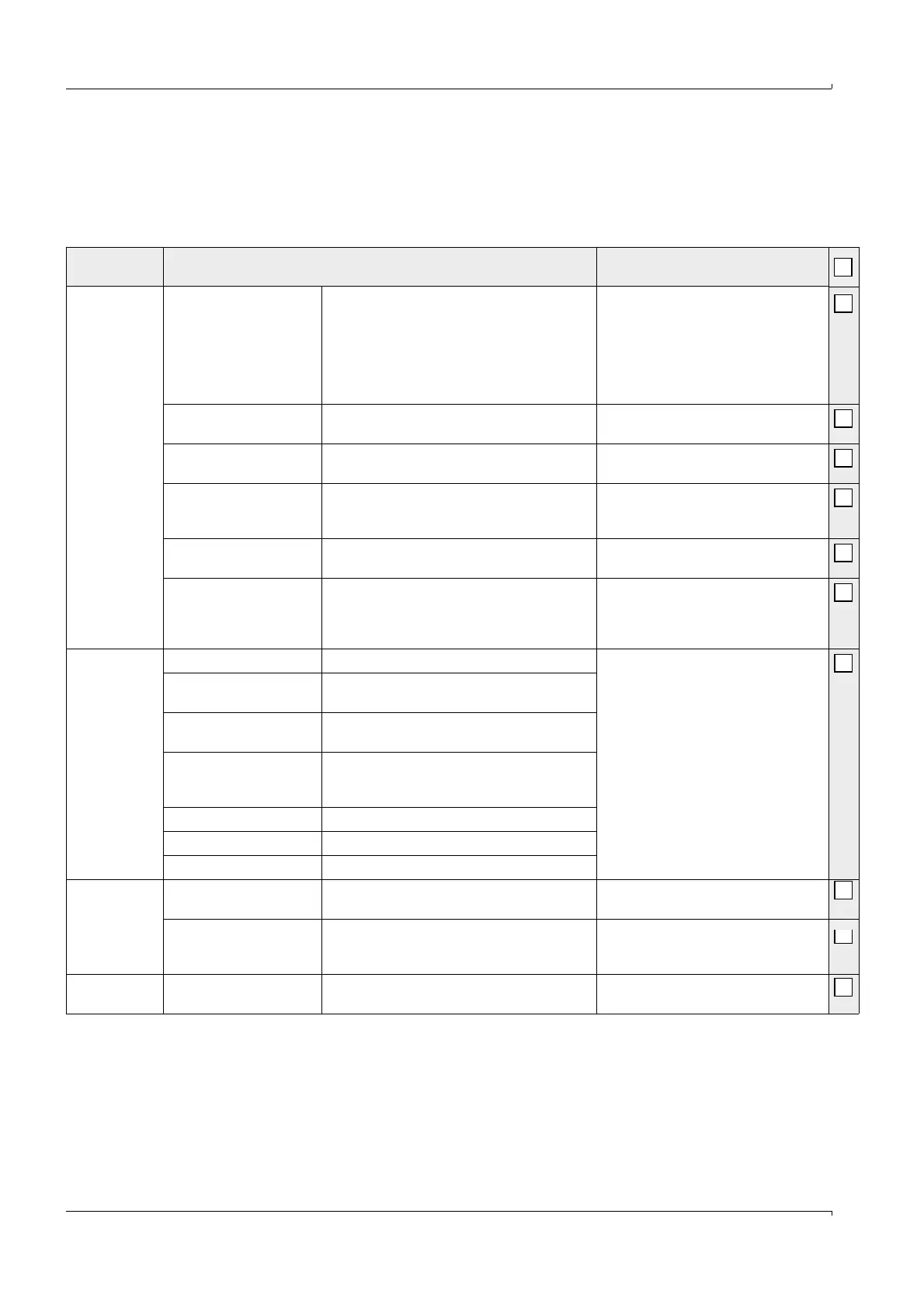
The following Table provides an overview of the project planning work to be carried out to
ensure the device is correctly installed and fully functional. You can use this Table as a
checklist by ticking off all the steps you have carried out.
Task Requirements Work step
Determine the
measuring and
installation
locations for the
device compo-
nents (
p. 51,
3.1.1)
Inlet and outlet sections
must be of sufficient length
Homogeneous flow distri-
bution
If possible, no bends, cross-section variations,
feed pipes, discharge pipes, flaps, or fittings
in the inlet and outlet sections
Comply with specifications for new
installations; choose the best possible
location for existing installations; if
necessary, determine flow profile in
accordance with DIN EN 132841;
if inlet/outlet sections are too short: Inlet
section > outlet section.
Accessibility, accident
prevention
Device components must be easily and safely
accessible
Provide platforms or pedestals when
necessary
Vibration-free installation Accelerations < 1 g Take appropriate measures
to eliminate/reduce vibrations
Ambient conditions Limit values in accordance with Technical Data If necessary:
Fit weatherproof covers/sun protection
Cover or insulate device components.
Purge air supply (for purged
FLSE100 only)
Clean intake air (as little dust as possible,
no oil, humidity, corrosive gases)
Choose the best possible intake location
Instrument air (only for
optional emergency air sets
for purged/cooled device
types)
Free from oil, dust and grease Choose the best possible installation
location
Choose the
device
components
Internal duct diameter Type of sender/receiver unit Choose components according to the
Configuration Table and information in
p. 17, 2.3.
If necessary, plan additional measures
to install the flange with tube
(
p. 60, 3.2.1).
Duct wall strength with
insulation
Nominal length of sender/receiver unit, flange
with tube
Internal duct pressure Type of sender/receiver unit; purge air unit
version (for purged FLSE100)
Gas temperature Type of sender/receiver unit (standard or inter-
nally cooled)
Purge air supply for purged FLSE100
Dust concentration Type of sender/receiver unit
Gas composition Material of duct probe and transducer
Installation locations Cable and purge air hose lengths
Plan the
calibration
openings
Accessibility Easy and safe Provide platforms or pedestals when
necessary
Distances to the measure-
ment level
No mutual interference
between calibration probe and FLOWSIC100
Ensure sufficient distance between the
measurement and calibration level
(approx. 500 mm)
Plan the voltage
supply
Operating voltage, power
requirements
In accordance with Technical Data in
p. 166,
6.1
Ensure sufficient cable cross-sections
and fuse