Assembly and Installation
FLOWSIC100 · Operating Instructions · 8012513/YSA5/V2-1/2016-07 · © SICK Engineering GmbH 79
Subject to change without notice
3.3.2.1 Control unit MCU-P with integrated cooling air supply (device type M-AC and H-AC)
Connect the mains cable to terminals L1, N and PE on the terminal strip.
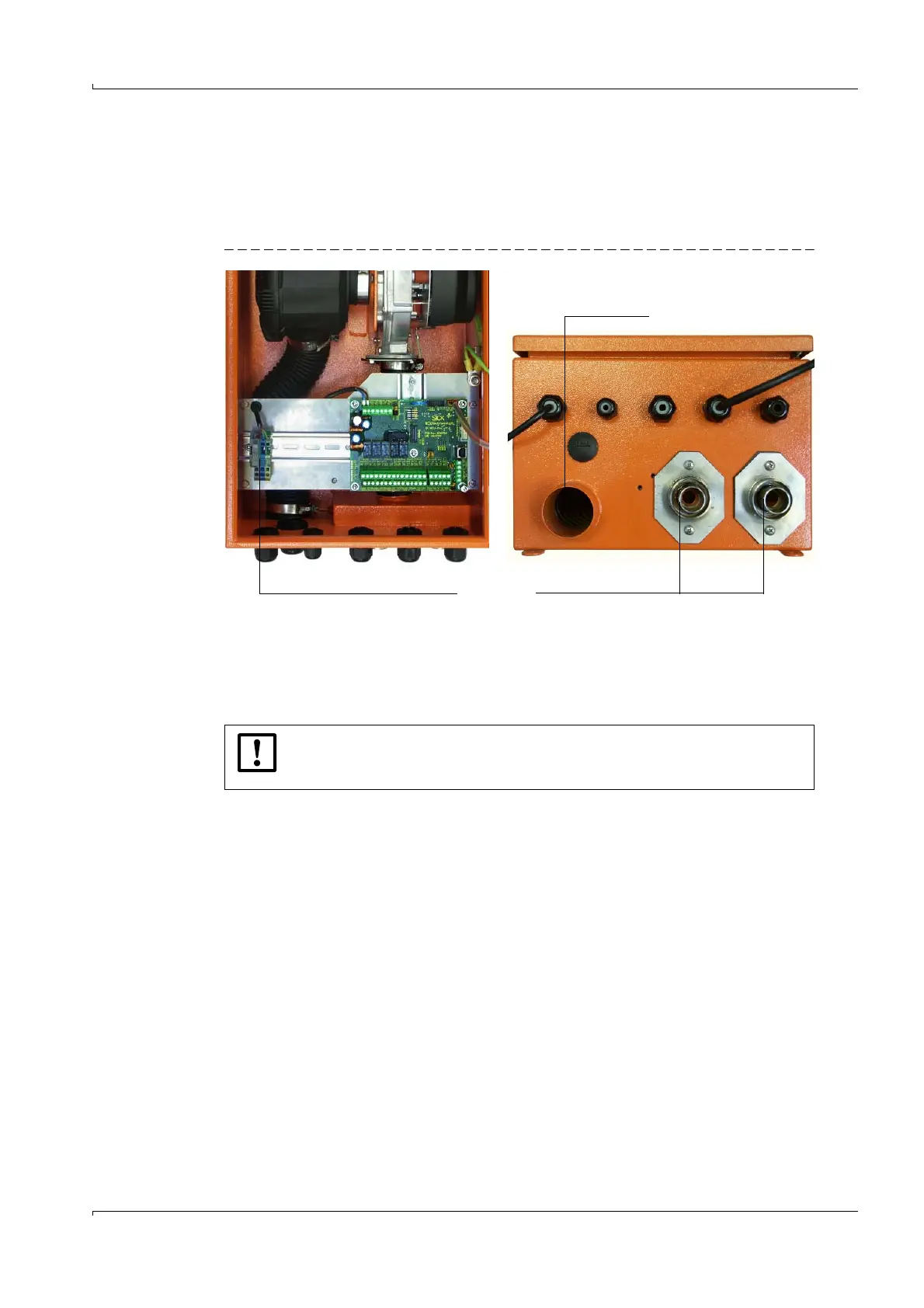
Connect the DN 25 purge air hose to the cooling air outlet on the underside of the
MCU-P (
p. 79, Fig. 49) and secure it with a strap retainer. The cooling air outlet in the
middle must be adjusted as displayed (correct if necessary).
Fig. 49 Underside of control unit with integrated cooling air supply
3.3.2.2 Separate cooling air supply in connection box (device type M-AC and H-AC)
Connect the mains cable to terminals L1, N and PE on the terminal strip.
Connect the DN 40 cooling air hose to the cooling air outlet on the underside of the
junction box (
Fig. 50) and secure it with a strap retainer. The cooling air outlet in the
middle must be adjusted as displayed (correct if necessary).
Terminals for mains connection Cooling air outlet DN 25
Cooling air
NOTICE:
Same connections at use of the separate cooling air supply in connection box
(
Fig. 49).