60 FLOWSIC100 · Operating Instructions · 8012513/YSA5/V2-1/2016-07 · © SICK Engineering GmbH
Assembly and Installation
Subject to change without notice
3.2 Assembly
All the assembly work has to be carried out onsite. This includes:
Installing the flanges with tube or glands for high-pressure versions
Fitting the control unit
Installing the purge air unit option
Fitting weatherproof covers
3.2.1 Installing the flanges with tube
3.2.1.1 Duct/pipe diameter > 0.5 m
Work to be performed
Measure out the installation location so that the planned installation angle is reached
(if mounting two flanges with tube, observe the diameter) and mark the installation
location.
Remove the insulation (if present).
Cut out suitable oval openings in the duct wall; drill suitably sized holes in brick and
concrete ducts (see the Annex for templates for openings).
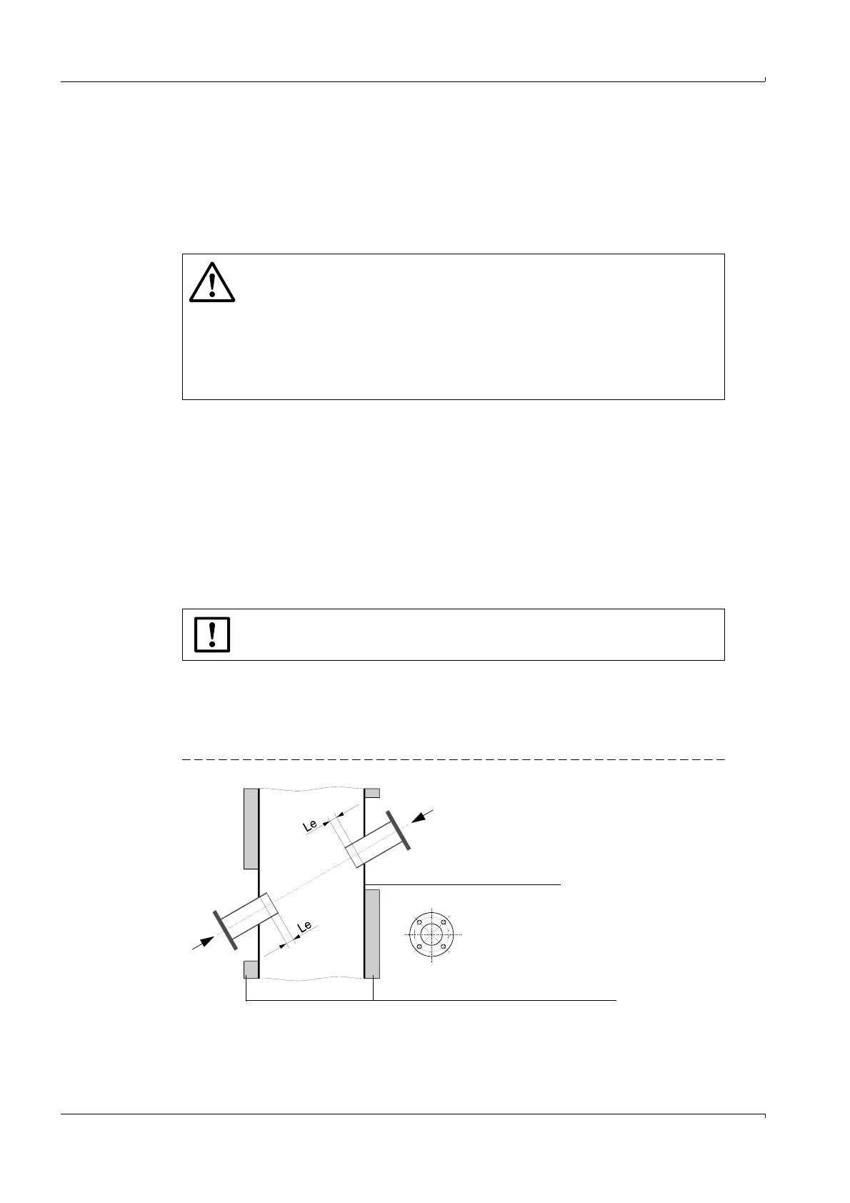
Insert the flange with tube in the opening as shown in Fig. 33,
– Observe the minimum draw-in length Le (>20 mm or as shown in Fig. 32 and Table)
– Roughly align it and tack it into position with a few spot welds
– With brick and concrete ducts, tack it to a holding plate (
p. 61, Fig. 34).
Fig. 33 Fitting the flanges with tube
WARNING:
● When carrying out assembly and installation work, observe the relevant
safety regulations and safety information in Section 1!
● Assembly and installation work on potentially dangerous installations (hot
or corrosive gases, high internal duct pressure) must only be carried out
when the system is shut down!
● Suitable protective measures must be taken to protect against local or
system-specific danger.
NOTICE:
Make sure parts cut off do not fall into the duct!
Duct / pipe wall
A
A
A
Insulation (remove around flange area)