Product Description
FLOWSIC100 · Operating Instructions · 8012513/YSA5/V2-1/2016-07 · © SICK Engineering GmbH 29
Subject to change without notice
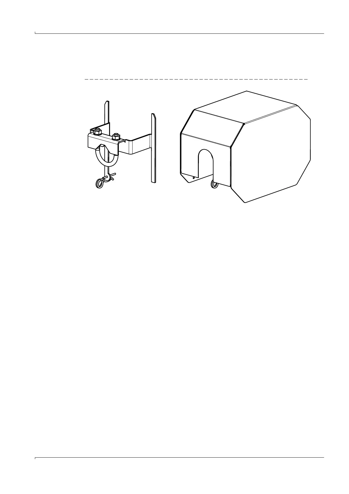
2.3.3 Weatherproof cover
The weatherproof cover protects the electronics of the sender/receiver unit against
sunlight and rain.
Fig. 16 Weather protection with holder
2.3.4 MCU control unit
The control unit has the following functions:
● Control of data transfer and processing the data from the sender/receiver units
connected via RS485 interface
● Signal output via analog outputs (measured value) and relay outputs (device status)
● Signal input via analog and digital inputs
● Voltage supply for the connected sender/receiver units
● Communication with host control systems via optional modules
System and device parameters can be set easily and conveniently via a USB interface
using a laptop and the user-friendly SOPAS ET operating software. The parameters are
stored reliably even in the case of a power failure.
The control unit is usually installed in a steel plate housing. It is available as 19" rack as an
option.