30 FLOWSIC100 · Operating Instructions · 8012513/YSA5/V2-1/2016-07 · © SICK Engineering GmbH
Product Description
Subject to change without notice
Versions
1 Control unit without cooling air supply
This control unit serves for connecting sender/receiver units FLSE100-M, H, PR, S, PM,
PH and PHS (optional for FLSE100-MAC and HAC).
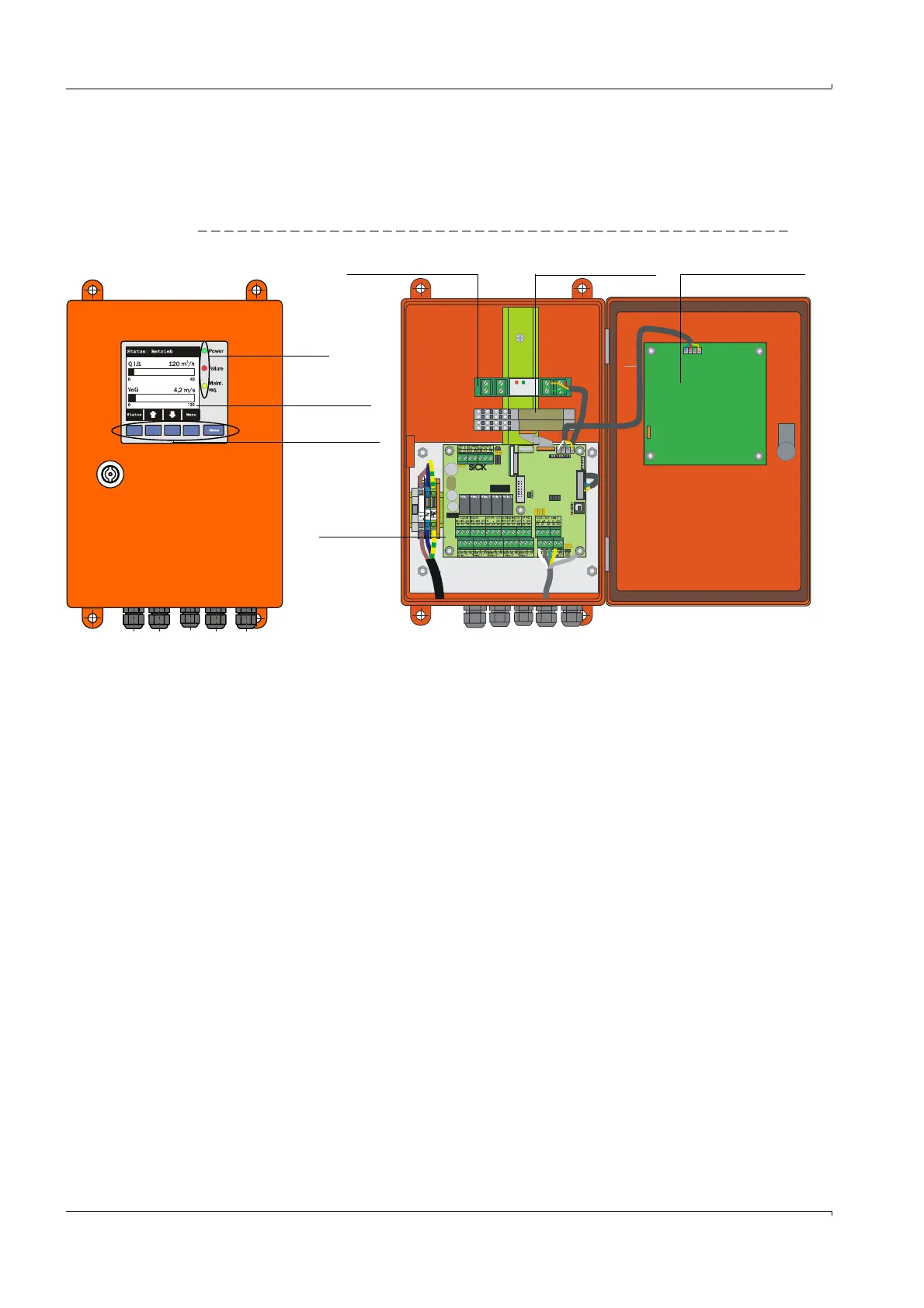
Fig. 17 Control unit MCU with options
2 Control unit with integrated cooling air supply (only for types M-AC and H-AC)
This version is additionally equipped with a purge air blower, air filter and purge air con-
nection for connecting DN 25 purge air hoses (must be ordered separately
p. 171,
Fig. 138) for sender/receiver units with internal cooling (types FLSE100-MAC and HAC).
LED
LC-Display
option
Control buttons
Connection
board
Interface module option
I/O module option
Display module option