Assembly and Installation
FLOWSIC100 · Operating Instructions · 8012513/YSA5/V2-1/2016-07 · © SICK Engineering GmbH 67
Subject to change without notice
Prerequisite for using the control unit MCU-P (for FLSE100-MAC and HAC)
Additionally to the general requirements the following is prerequisites apply:
● Install the MCU-P at a location with clean air whenever possible. The intake tempera-
ture must match the values specified in the Technical Data (
p. 166, 6.1). If necessary,
lay an air intake hose at a location where conditions are more favorable.
●
The purge air hoses DN25 (Part No. 7047535 and 7047536) to both sender/receiver
units should be as short as possible They must be of equal length (max. hose length in
each case 10 m).
● The purge air hoses should be laid in such a way that water cannot collect.
Additional requirements when the control unit MCU must be installed more than 10 m
away from the measuring point:
– Use of a separate cooling air unit in the connection box (dimensions and assembly
dimensions as for MCU-P; Part No. 2070816 and 2070817)
– Use of the control unit in version MCU-N (without integrated blower unit)
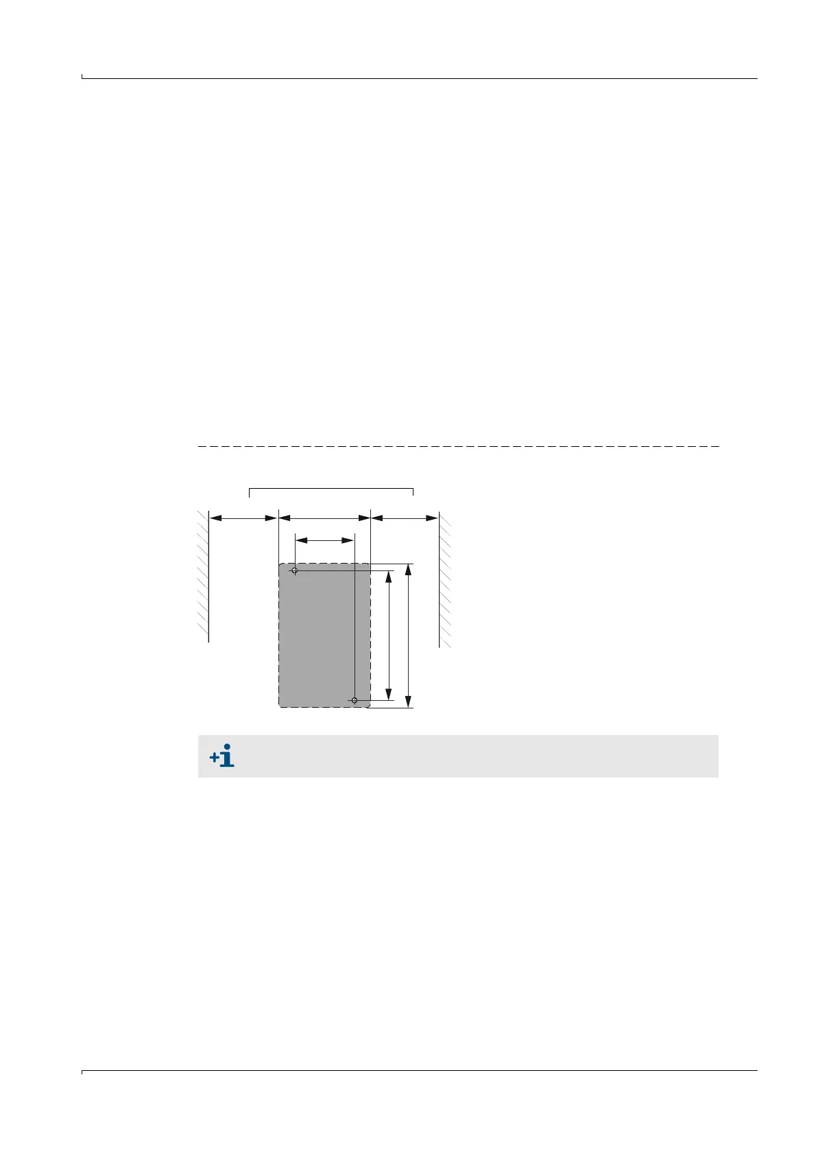
3.2.3 Installing the junction box
Install these subassemblies on a level base plate (secure with 2 M4x20 bolts).
Fig. 39 Junction box assembly dimensions
3.2.4
Installing the sender/receiver units
Check the following points before installing the sender/receiver units in the prepared
flange tubes:
● Connections and sender/receiver units must be compatible (
p. 28, 2.3.2).
● The inside walls of the connections must be completely free from welding beads.
● Optional: Fitting an impact protector on the sender/receiver unit (
p. 72, 3.2.8)
Push the sender/receiver units into the flange tubes and fit these on the flange with the
delivered bolts and the optional structure-borne noise damping set.
Suitable fastening sets are available for installation on stone / concrete
ducts.
Clearance for cable
> 150 > 15080
52
M4
113
125