Assembly and Installation
FLOWSIC100 · Operating Instructions · 8012513/YSA5/V2-1/2016-07 · © SICK Engineering GmbH 97
Subject to change without notice
3.3.6 Connecting the control unit MCU
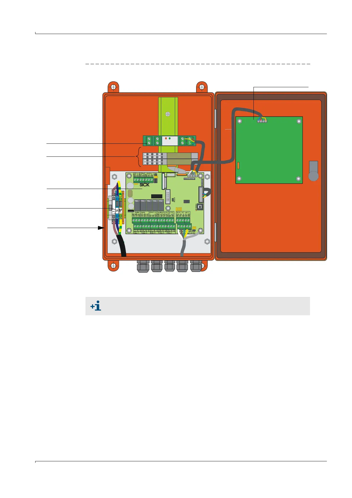
Fig. 68 Component layout in the MCU (without cooling air supply, with options)
Necessary work
Connect the connection cable as shown in Fig. 73.
Connect the cables for status signals (operation/malfunction, limit value, warning,
maintenance, check cycle), analog output, analog and digital inputs according to the
requirements.
Connect mains cable to terminals L1, N, PE (
Fig. 68).
Close off unused cable ducts with dummy plugs.
Display module option
I/O module option
Power supply unit
(behind connection
board)
Terminals for power
supply
Processor board
Option
Interface module
We recommend using a bus wiring configuration when the distance between
the sender/receiver units and the control unit is large.