96 FLOWSIC100 · Operating Instructions · 8012513/YSA5/V2-1/2016-07 · © SICK Engineering GmbH
Assembly and Installation
Subject to change without notice
Purge air supply for purged sender/receiver units FLSE100-PM, PH, PHS
To minimize corrosion when using corrosive gases, ensure the nominal lengths of the
sender/receiver units are at least one length longer than the nominal lengths of the
flanges with tube (
p. 27, 2.3.1.3).
Check/ensure the purge air supply is in operation.
Connect the purge air hoses, to do this, connect the hose clamp loosely on the free
hose end, connect the purge air hose to the purge air connection on the sender/
receiver units, and secure it with the hose clamp.
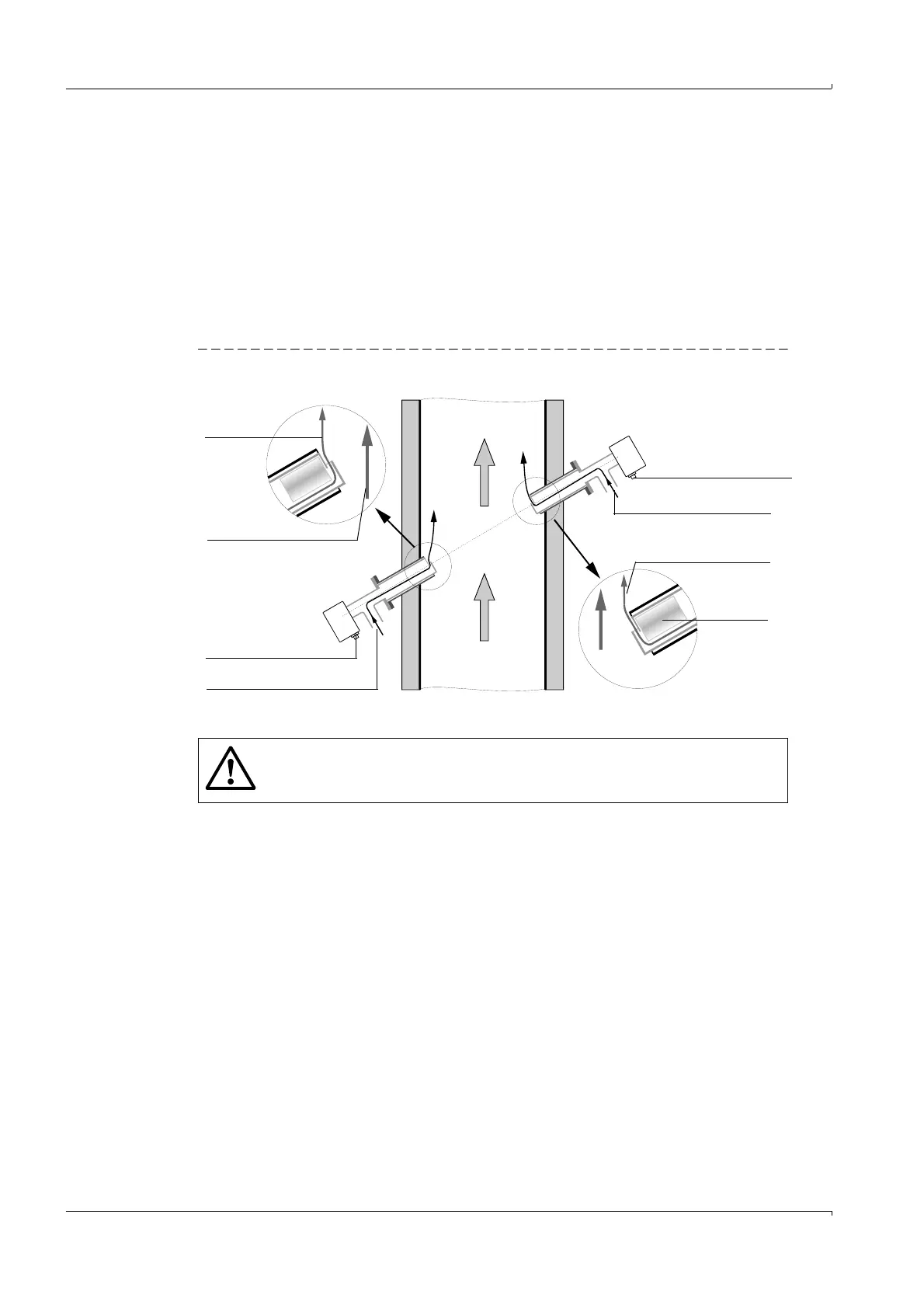
Check/ensure the purge air is fed from below and the purge air flows out in the direc-
tion of the gas flow.
Fig. 67 Alignment of cable connection and purge air supply for purged sender/receiver units (shown for type
FLSE100 PM/PH, fitted on a vertical duct)
Installation and electrical connection
Remove the blind plug from the flange.
Insert the sender/receiver units in the flanges with tube as previously described and
screw the components together.
Connect the cable to the control unit to the plug-in connector on the sender/receiver
unit.
Duct
Gas flow
Ultrasonic
transducer
Discharged
purge air
Gas flow
Cable connection
Purge air feed
Cable connection
Purge air feed
Discharged
purge air
WARNING:
Only install the sender/receiver units when it is safe to do so (for example,
when the system has been shut down, see
p. 9, 1.3.3).