14 FLOWSIC100 · Operating Instructions · 8012513/YSA5/V2-1/2016-07 · © SICK Engineering GmbH
Product Description
Subject to change without notice
Set for connecting and operating a temporary emergency air supply of instrument air (to
be provided by customer) for externally purged sender/receiver units.
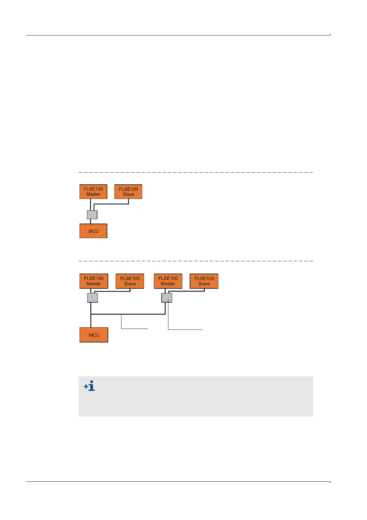
2.2.2 Communication between sender/receiver units and control unit
Standard version
The two sender/receiver units work as master and slave. The master FLSE has a second
interface to be able to completely separate communication to the slave FLSE and to the
MCU. The master triggers the slave and controls measurement. The MCU can request the
measured values from the master units independently of the measuring cycle
(asynchronous).
For the cabling, the junction box used to separate the interfaces has to be installed on the
master FLSE. The junction box is optional for FLOWSIC100 types PR and S (for longer cable
lengths).
Fig. 2 Standard version (1 sensor pair)
Bus version with several measuring systems connected
Fig. 3 Bus connection FLSE100 - MCU (2 sensor pairs)
With the bus version, two autonomous measuring paths (2 x 2 FLSE100) can be connected
to a control unit MCU for 2-path-measurement. The MCU computes both measuring paths
to one measuring result.
● For bus wiring, the set termination set at the factory must be deactivated in
those system components not at the line end (see Service Manual Section
3.1).
● Other sensor types (e.g. sensor for dust measurement) can also be con-
nected to the MCU.