Assembly and Installation
FLOWSIC100 · Operating Instructions · 8012513/YSA5/V2-1/2016-07 · © SICK Engineering GmbH 63
Subject to change without notice
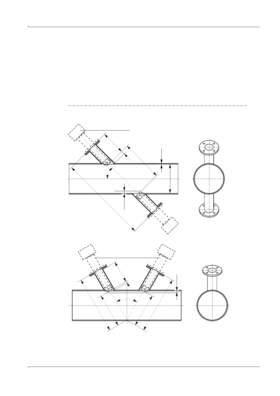
3.2.1.2 Duct/tube diameter < 0.5 m
The work is generally the same as for larger diameters. The difference with small diameters
is that installing the flanges and sender/receiver units can have a greater impact on the
flow characteristics. To minimize this impact, the flange tubes should not be inserted in the
pipeline, but rather mounted and welded flush on the outside.
Two options are available for installation (
Fig. 36):
● On two sides
● On one side, using the sound reflection on the opposite inside wall. This solution can be
used with very small ducts to lengthen the measuring path, or if access is only possible
from one side.
Fig. 36 Fitting the flanges with tube
Carry out the following before fitting the flanges with tube:
Fitting on both sides
Fitting on one side
Sender/receiver unit
*
*
Type FLSE100-M is shown
NL
w
x
Di
45°
±0.5°
Di = 0.15 ... 0.5 m
Sender/receiver unit
*
N
L
x
60°
±0.5°
b
(=10 mm)
b
(=8 mm)
L
FF
F
1
L
1
L
2
F
2
L = L1 + L2
FF = F1 + F2