62 FLOWSIC100 · Operating Instructions · 8012513/YSA5/V2-1/2016-07 · © SICK Engineering GmbH
Assembly and Installation
Subject to change without notice
When fitting two flanges with tubes, align both exactly to each other after tacking using
a suitable tube (for smaller ducts) or using the SICK adjustment aid (can be provided on
loan) (see Fig. 35).
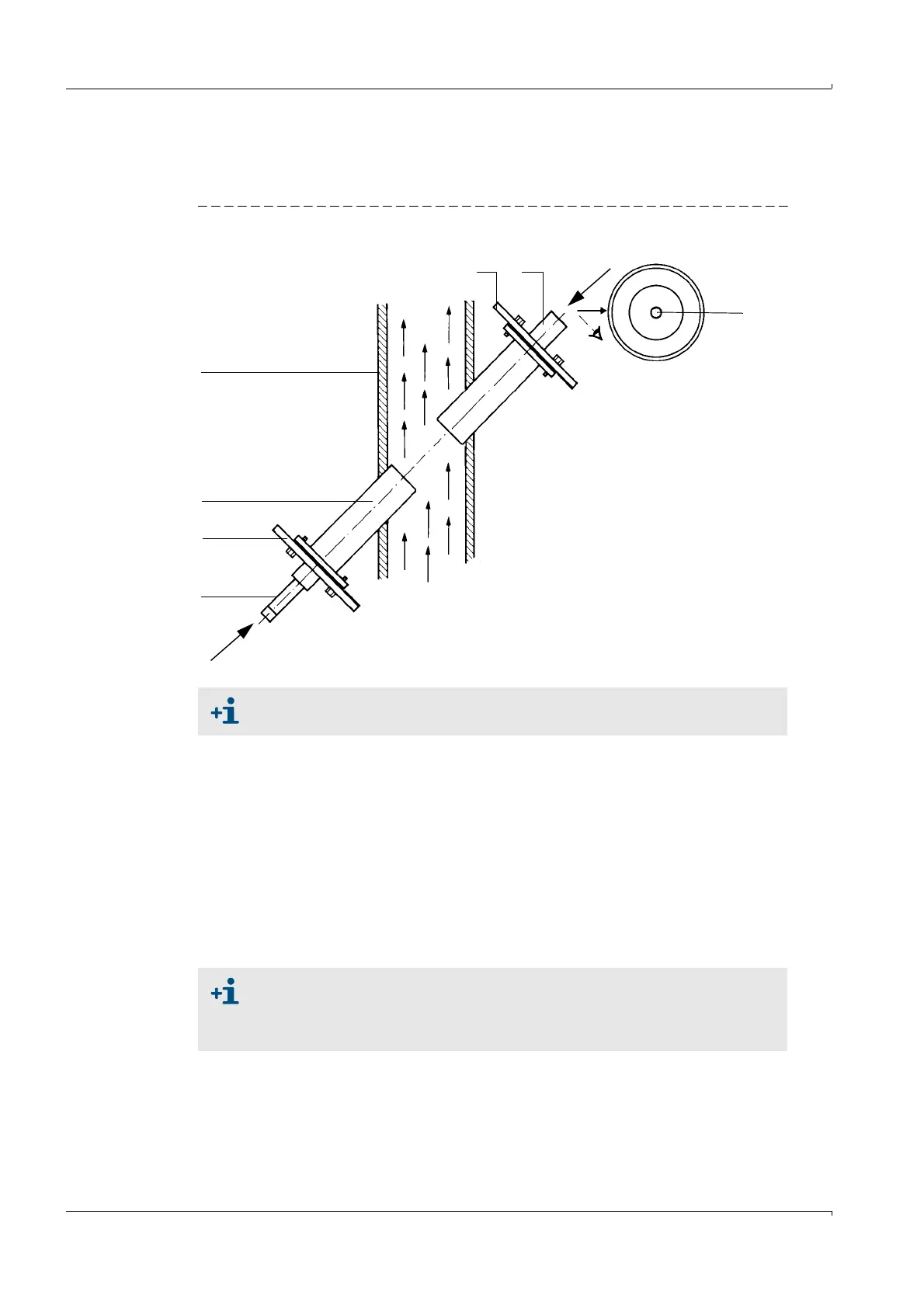
Fig. 35 Aligning the flange using the optical alignment device
Weld on the flange tubes, while constantly ensuring that the alignment is exact (correct
if necessary). When using the alignment device, first reposition the flange plate with
lamp and flange plate with target optics before welding the second flange tube on.
Measure and note the installation angle for configuring the parameters later.
Measure and note the distance between the two flanges (dimension F-F in Fig. 31) and
make a note of it for configuring the parameters later. The DME 2000 distance sensor
from SICK can be used (consult SICK, if required) for this purpose.
With thin-walled ducts/lines, provide suitable brackets/reinforcement to prevent distor-
tion and vibration (
p. 61, Fig. 34).
Seal the flange with a blind plug (optional).
Insulate the flange tube (if necessary).
Align the flange with target optics so that the light spot of the lamp appears
in the center of the target optics.
1 Lamp in adjusting device
2 Lamp flange plate
3Flange tube
4Duct
5 Target optic flange plate
6 Target optic, visor
7 Sight with optimum alignment
4
3
2
1
5
7
A
A
6
● When mounting two flanges with tube, the alignment of the two flange
tubes has priority over the installation angle.
● Distortions as a result of temperature changes or mechanical stresses can
change the measuring path.