164 FLOWSIC100 · Operating Instructions · 8012513/YSA5/V2-1/2016-07 · © SICK Engineering GmbH
Maintenance
Subject to change without notice
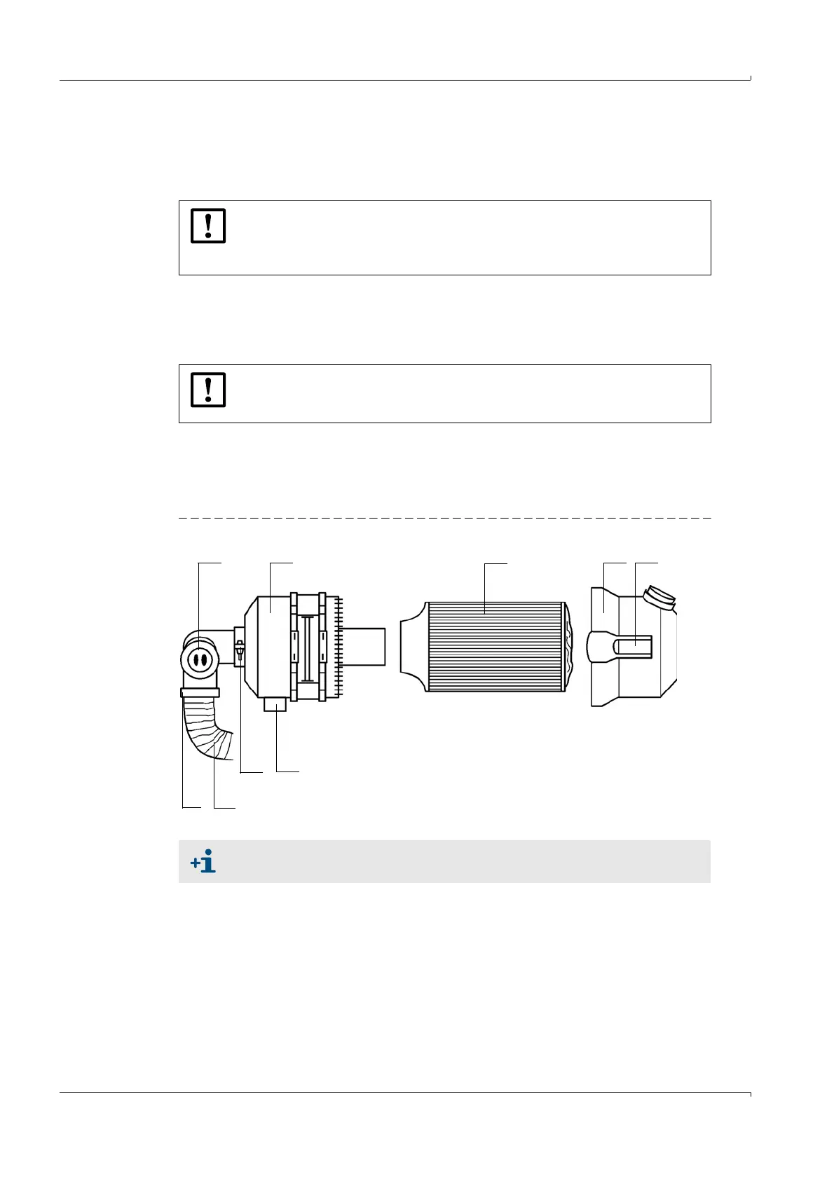
5.4.2 Replacing the filter element
Have a new filter element (2) available.
Loosen the hose clamp (6) on the purge air hose (7) and remove the hose and secure
the hose at a clean location.
Remove any dust from the outside of filter housing (1).
Press the two quick-release locks (4) on filter housing cover (3) to remove it.
Remove filter element (2) by twisting it counterclockwise.
Clean the inside of the filter housing and filter housing cover with a cloth and brush.
Insert the new filter element by twisting it clockwise.
Mount the filter housing cover and ensure it is aligned correctly with the housing, and
snap the quick-release locks into position.
Connect the purge air hose to the filter outlet again using the hose clamp.
Fig. 134 Replacing the filter element
NOTICE:
Place the end of the hose in a safe place so that impurities cannot be sucked
in (risk of severe damage to the blower). Unfiltererd air enters the sender/
receiver unit during this time.
NOTICE:
Only use a cloth soaked in water to wet-clean the parts and then dry the parts
thoroughly.
Spare part: Filter element Micro-Top element C11 100, Part No. 5306091
9
1234
8
7
65
1 Filter housing 6 Hose clamp
2 Filter element 7 Purge air hose
3 Filter housing cover 8 Hose clamp
4 Quick-release lock 9 Low-pressure sensor
5Air intake gland