154 FLOWSIC100 · Operating Instructions · 8012513/YSA5/V2-1/2016-07 · © SICK Engineering GmbH
Start-up and Parameter Settings
Subject to change without notice
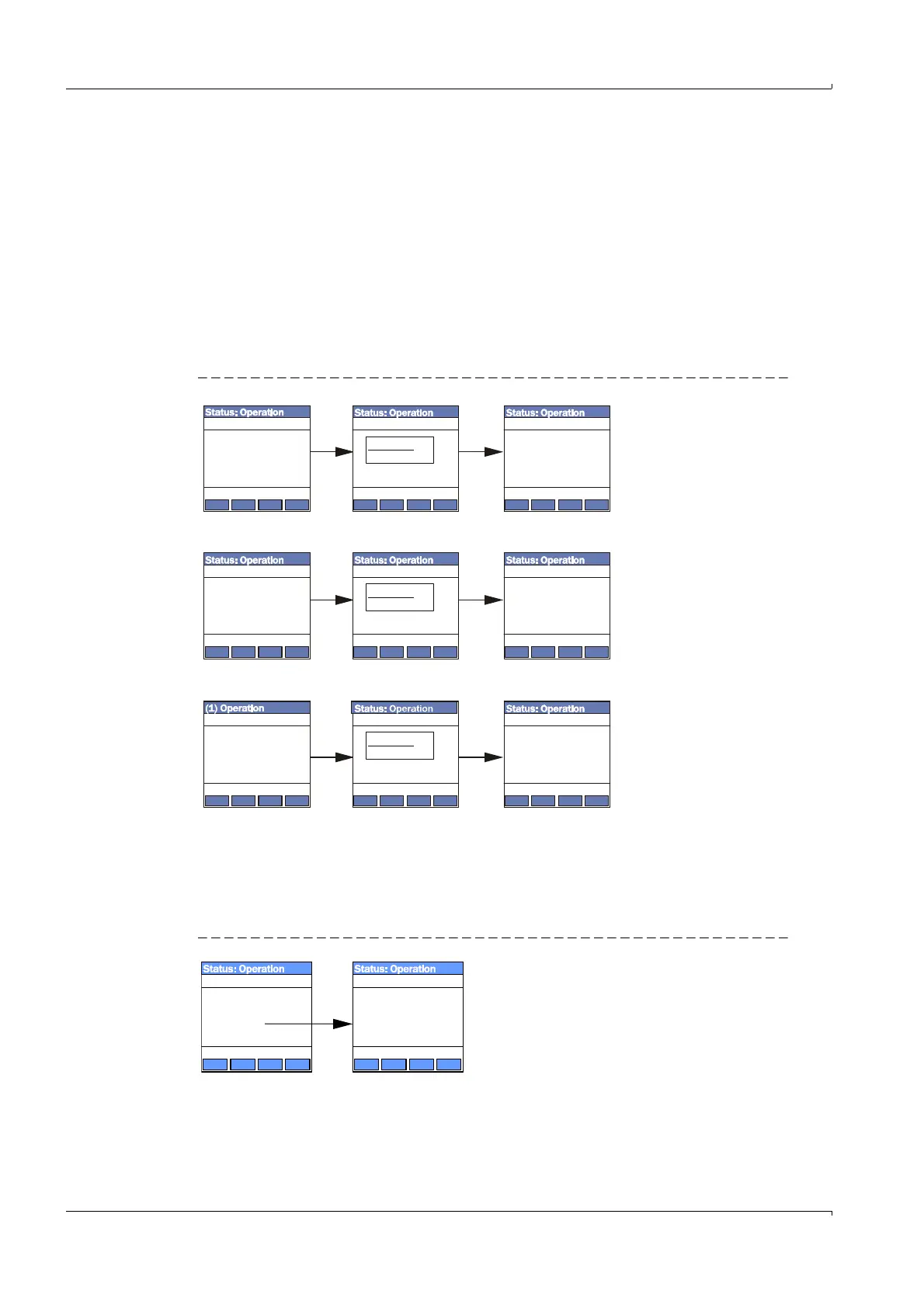
4.4.3 Configuring
Parameters for input / output (analog input / output) or installation (measuring path
length, installation angle, duct diameter) can be changed with the following procedure:
Go to the appropriate submenu, select the line ‘‘Limit Low” or ‘‘Limit High” and press
‘‘Enter”
The valid range is displayed in the fields ”Min“ and ”Max“
Enter the default password ”1234“ with the keys ”^“ (scrolls from 0 to 9) and/or ”
“
(moves the cursor right).
Select the desired value for ”Min“ and ”Max“ with the keys ”^“ and/or ”
“ and confirm
with ”Save“.
The selected value is saved to the device.
Fig. 130 Menu structure for configuration
4.4.4
Changing the application setting
In the menu ‘‘I/O (MCU)” select submenu ‘‘I/O Parameter”, select line ‘‘MCU Vari-
ant” and confirm with ‘‘Enter”.
Select "FL100 2 path” in the ‘‘MCU Variant” submenu and confirm with ‘‘Enter”.
Fig. 131 Menu structure for selecting two-path measurement
1 Path Length
2 Installation Angle
3 Cross Section Area
Parameter
/sensor/1/para/
Back Enter
1 Limit Low
2 Limit High
3 Live Zero
AO 1 Parameter
/io/para/ao/1
Back Enter
1 Limit Low
2 Limit High
AI 1 Parameter
/io/para/ai/1/
Back Enter
Limit Low
/io/para/ai/1/
Password
1234
Limit Low
Limit Low
Limit Low
/io/para/ai/1/
/sensor/1/para/
/io/para/ao/1/
Limit Low
/io/para/ao/1/
Back Save
Password
1234
Limit Low
/sensor/1/para/
Password
1234
0.000 Pa
6.2 m
0000.00 m³/h
Min:
Min:
Min:
Max:
Max:
Max:
Back Save
Back Save
Back Save
Back Save
Back Save
1 AO Parameter
2 AI Parameter
3 MCU Variant
1 FL100 1 path
2 FL100 2 path
3 Unlimited
I/O Parameter MCU Variant
/io/para/ /io/para/var/
Back Enter
Back Enter