70 FLOWSIC100 · Operating Instructions · 8012513/YSA5/V2-1/2016-07 · © SICK Engineering GmbH
Assembly and Installation
Subject to change without notice
Installation work
Prepare the bracket in accordance with Fig. 40 (page 69).
Secure the purge air unit with 4 bolts (M8).
Check the filter element is in the filter housing, insert when necessary.
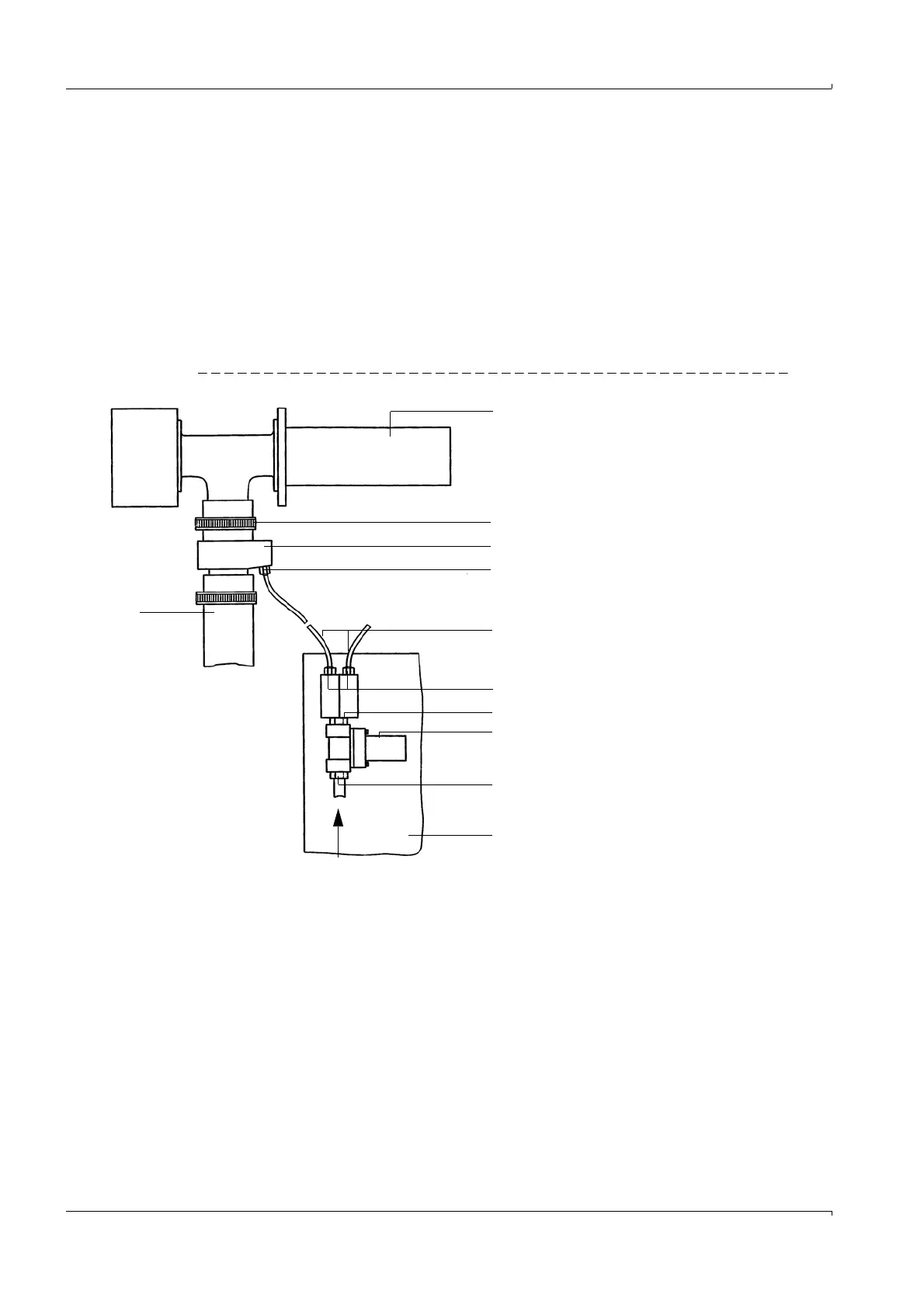
3.2.7 Installing the emergency air supply option for device types PM, PH and PH-S
The subassemblies are delivered pre-assembled. Connect adapters (3) to the purge air
connections of the S/R units and fasten with the hose clamps (scope of delivery) (
Fig. 41).
Fit and wire the solenoid valve on the purge air base plate (see connection
p. 93, 3.3.4.2,
Fig. 64 - Fig. 66). Insert compressed air hoses (5) paired in quick-connectors (6) and fasten
on quick connector (4). These must always have the same length.
Fig. 41 Connection - emergency air supply for one purge air unit
1 Sender/receiver unit
2 Hose clamp (scope of delivery for
emergency air supply)
3Adapter
4 Quick connector
5 Compressed air hose
6 Quick connector, paired
7 Reducer
8 Solenoid valve
9 Coupling
10 Purge air base plate
11 Purge air hose
1
2
3
5
6
7
8
9
10
11
4
Compressed air onsite