Assembly and Installation
FLOWSIC100 · Operating Instructions · 8012513/YSA5/V2-1/2016-07 · © SICK Engineering GmbH 71
Subject to change without notice
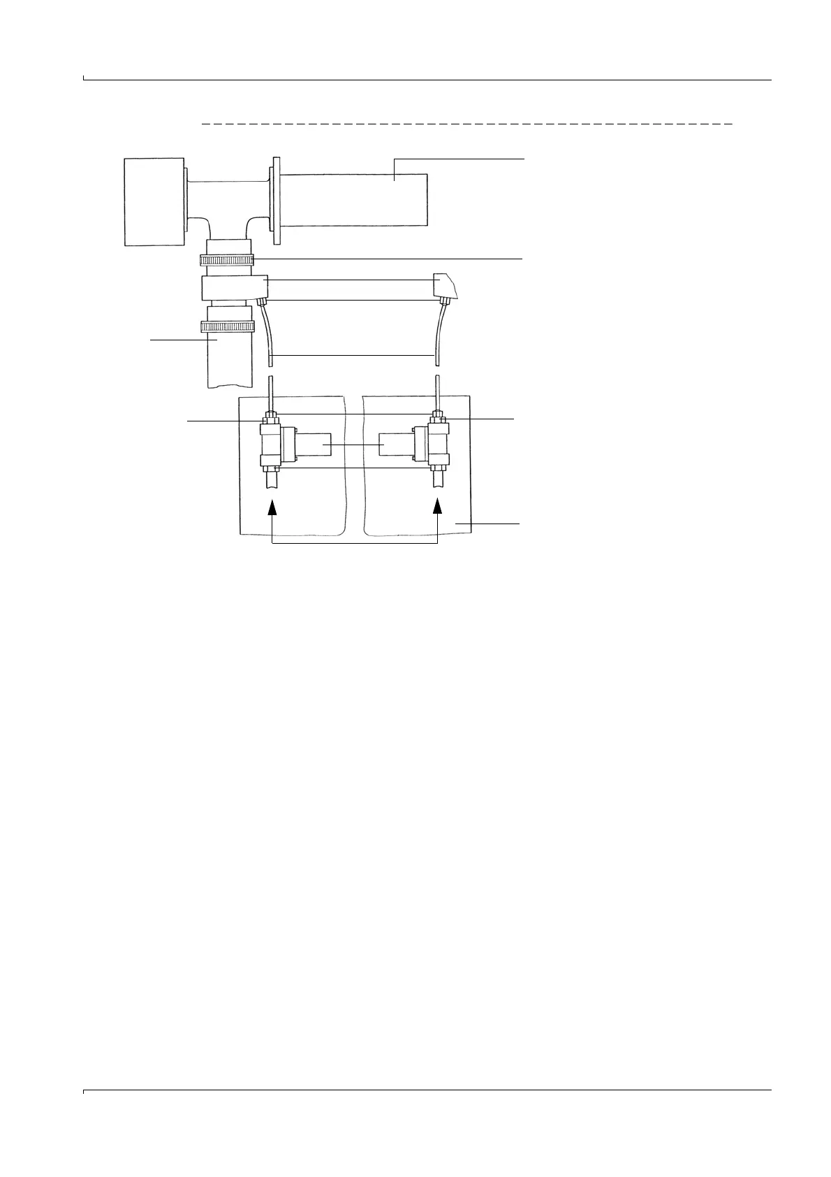
Fig. 42 Connection - emergency air supply for two purge air units
Insert the backflow valves (for overpressure in duct) directly on the Y-distributor of the
purge air blower (remove the existing purge air hose) and fasten with hose clamps (Fig. 43).
1 Sender/receiver unit
2 Hose clamp (scope of delivery for emergency air
supply)
3Adapter
4 Quick connector
5 Compressed air hose
6 Reducer
7 Solenoid valve
8 Coupling
9 Purge air base plate
10 Purge air hose
1
2
3
5
9
10
4
4
7
8
6
6
Compressed air onsite