64 FLOWSIC100 · Operating Instructions · 8012513/YSA5/V2-1/2016-07 · © SICK Engineering GmbH
Assembly and Installation
Subject to change without notice
Cut out suitable oval openings in the duct wall (see Annex for templates).
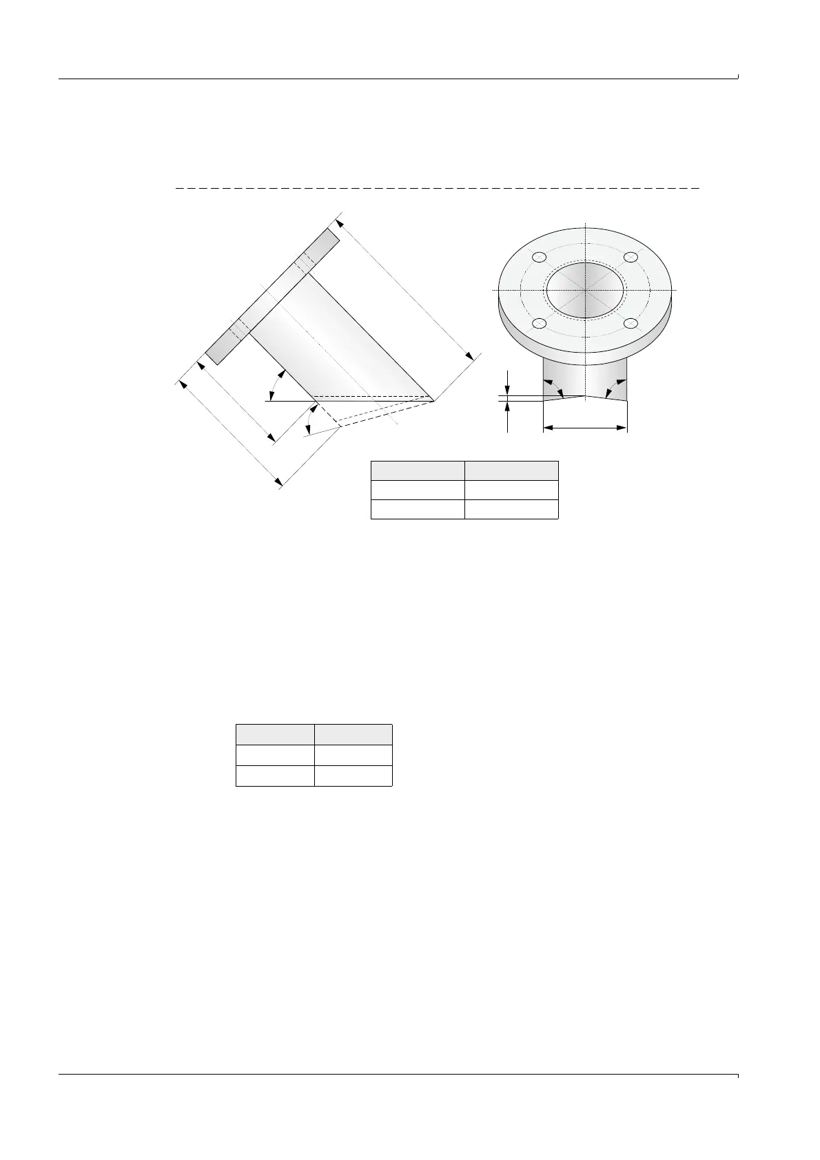
Bevel the flange tubes at an angle of 45
° or 60°.
If necessary, adapt the flange tubes to the wall curvature as shown in Fig. 37.
Fig. 37 Adapting the flanges with tube
Flange tube length L
F
(L
F45
, L
F60
) depends on installation angle , wall thickness w and
nominal length NL (
Fig. 36,
Fig. 37). This correlation is expressed by the following
formulas:
Di (mm) a (mm)
500 ... 290 0
290 ... 150 3
L
F
45°
60°
(87°) (87°)
48,3
a
L
F60
L
F45
L
F
NL x+=
L
F45
L
F
48.3–=
L
F60
L
F
27,9–=
x
48 3 35+
2 tan
------------------------
wb+
sin
------------------
–=
b
45° 10
60° 8