58 FLOWSIC100 · Operating Instructions · 8012513/YSA5/V2-1/2016-07 · © SICK Engineering GmbH
Assembly and Installation
Subject to change without notice
Maximum possible wall (and insulation) thickness as a function of the nominal length of
the flanges with tube, flange size (pipe diameter D
R
) and installation angle (Le = 20 mm):
Shortening the measuring path
It may be necessary to shorten the measuring path to prevent problems in signal
transmission in certain cases, e.g. when using types FLSE100H, HAC, PH or PHS with high
dust concentrations (
p. 17, 2.3.1). This can be achieved by installing extended flange
tubes and/or flanges with tube across the secant.
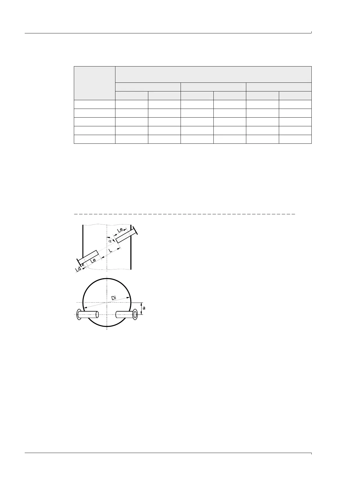
The installation conditions are shown in Fig. 32 and in the following Table.
Fig. 32 Installation across secant
Nominal length
L
F
[mm]
Maximum wall and insulation thickness w [mm]
D
R
= 114.3 D
R
= 76.1 D
R
= 48.3
= 45° = 60° = 45° = 60° = 45° = 60°
125 15 45
200 499768110
350 112 196 155 227 174 240
550 253 369 297 400 315 413
750 395 543 438 573
L = Active measuring path
Le = 20 ... 500 mm
a
max
= Di / 4
a = 60°
Ld as in Fig. 31
With a = a
max
and circular ducts
then (= 60°)
Di
max
= L +2 Le + Ld