Specification
FLOWSIC100 · Operating Instructions · 8012513/YSA5/V 2-1/2016-07 · © SICK Engineering GmbH 177
Subject to change without notice
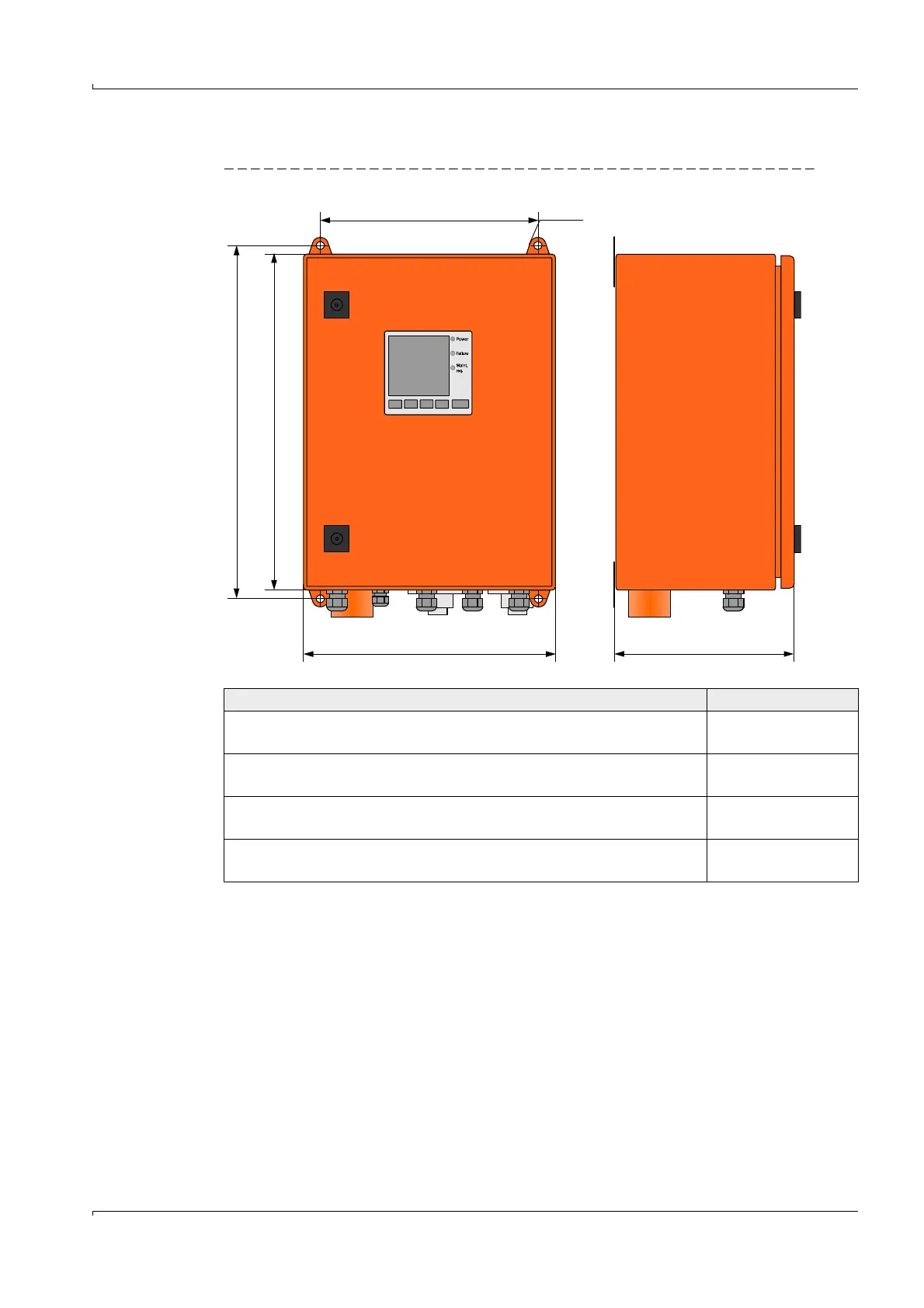
Control unit MCU-P (with integrated cooling air supply)
Fig. 145 MCU-P (shown with display module option)
Designation Part No.
MCU-PWONN00000NN control unit in wall housing (orange),
Supply voltage 90 ... 250 V AC, with purge air unit, without display
1040668
MCU-PWODN00000NN control unit in wall housing (orange),
Supply voltage 90 ... 259 V AC, with purge air unit, with display
1040676
MCU-P2ONN00000NN control unit in wall housing (orange),
Supply voltage 24 V DC, with purge air unit, without display
1040670
MCU-P2ODN00000NN control unit in wall housing (orange),
Supply voltage 24 V DC, with purge air unit, with display
1040678