Assembly and Installation
FLOWSIC100 · Operating Instructions · 8012513/YSA5/V2-1/2016-07 · © SICK Engineering GmbH 99
Subject to change without notice
1)
:Closed in current-free state (normal closed)
2)
:Open in current-free state (normal opened)
3)
:Only use after agreement with manufacturer
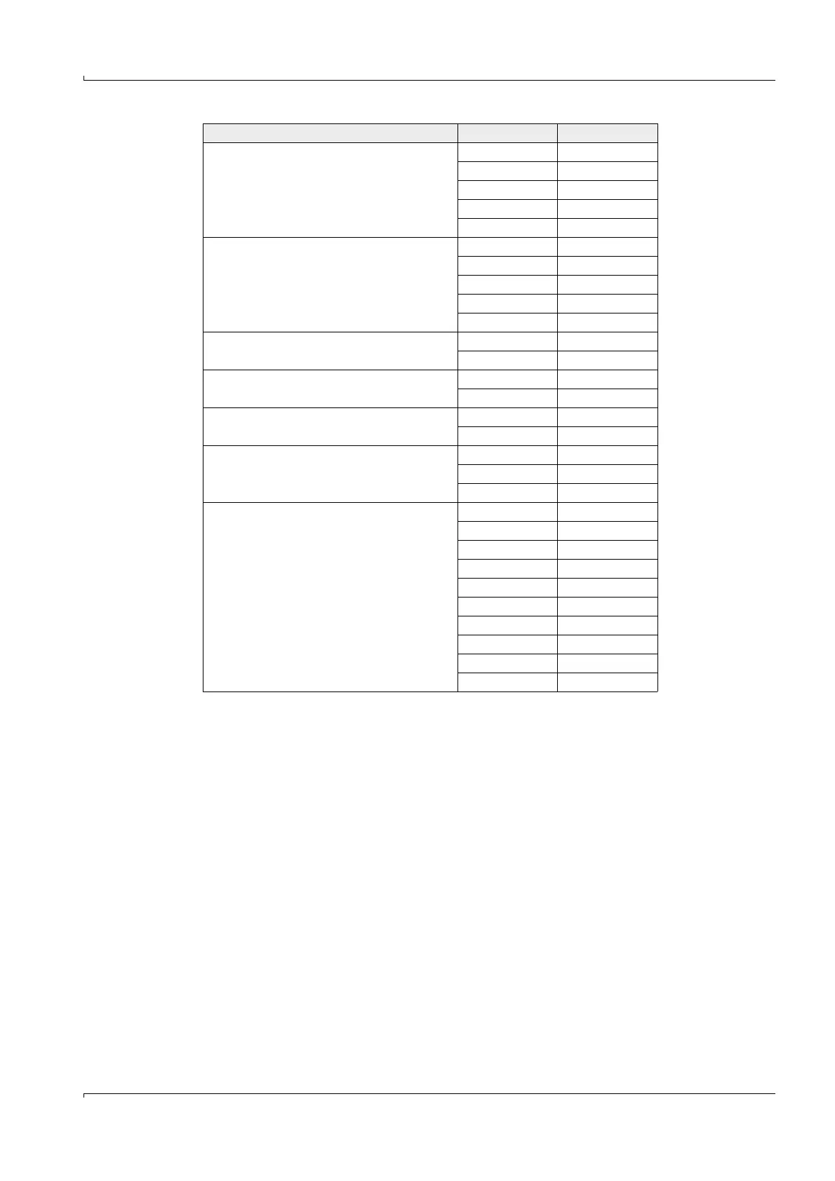
Master sender/receiver unit (unit 1) connections +24 31
-24 32
RS485 A 33
RS485 B 34
scr. 35
Master sender/receiver unit (unit 2) connections +24 36
-24 37
A38
B39
scr. 40
Input voltage supply 24V DC
3)
24 V 41
gnd 42
Output voltage supply 24 V DC
3)
24 V 43
gnd 44
Input 30 V electr. isolated + 45
-46
RS232/485
3)
tx/A 51
rx/B 52
gnd 53
Interface 1 A 71
B72
gnd 73
+Us 74
-Us 75
gnd 76
imp+ 77
imp- 78
res 1 79
res 2 80
Function Connection Terminal No.