100 FLOWSIC100 · Operating Instructions · 8012513/YSA5/V2-1/2016-07 · © SICK Engineering GmbH
Assembly and Installation
Subject to change without notice
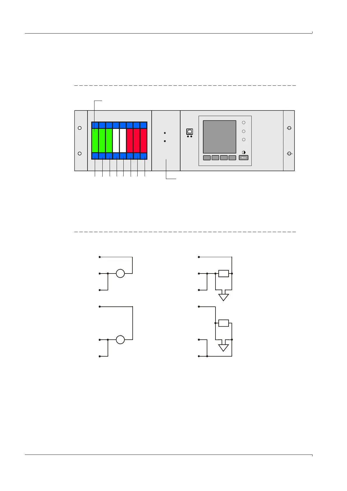
Fitting and connecting optional I/O modules
Connect the optional analog and digital modules to the slots on the module carrier as from
slot 1 next to each other in the sequence AO
AI DO DI. If single module types are
not present, the next one follows according to the specified sequence.
Fig. 70 Slots for optional modules
Connection is made to terminals 101 - 180 on the backplane.
The following shows the I/O module connection for slot 1 as an example.
Connect the I/O modules to slots 2 -8 in the same manner.
– Analog module connection
Fig. 71 Analog module on slot 1 (terminals 101 - 110)
REQUEST
INTERFACE-MODULE
I/O-MODULE
POWER
ERROR
TxD RxD
Slots for optional I/O modules
8
7
65 1
2
3
Slot
4
Slot for interface module option
101 a
102 b
103 c
104 d
105 a
106 b
107 c
108 d
109 -gnd
110 scr
101 a
102 b
103 c
104 d
105 a
106 b
107 c
108 d
109 -gnd
110 scr
+
+
+
+
-
-
-
-