56 FLOWSIC100 · Operating Instructions · 8012513/YSA5/V2-1/2016-07 · © SICK Engineering GmbH
Assembly and Installation
Subject to change without notice
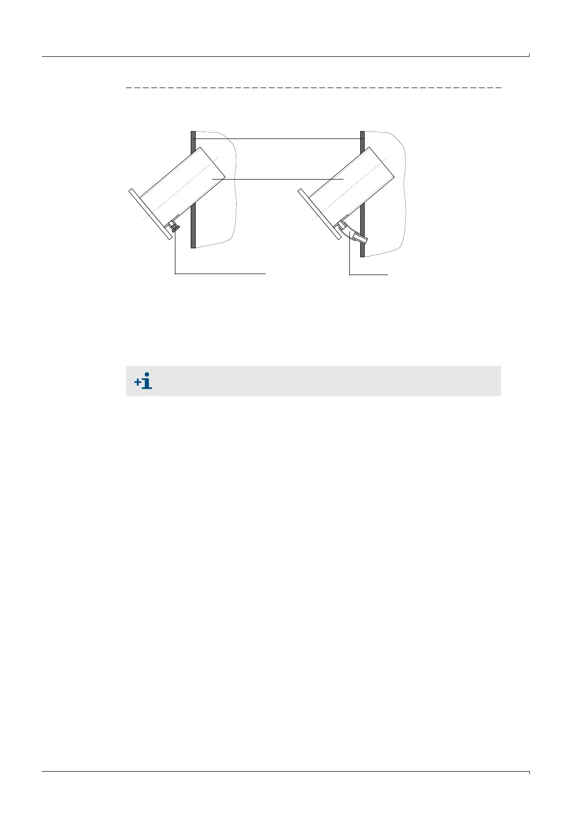
Fig. 30 Condensate drain / backflow
Using the sender/receiver units with high dust contents (> 1 g/m³)
The measuring path must be as short as possible. This requires installing the sender/
receiver units at an angle of 60° to the flow direction.
In addition, fit impact protectors on the downstream sender/receiver unit (
p. 15, Fig. 4) on
types FLSE100-PH / PHS and H / HAC to prevent particles impacting on the transducer
surface causing malfunctions impairing measuring behavior.
Duct wall
Flange with
tube
Opening with plug
Condensate drain
Hose
Condensate backflow
See
»Shortening the measuring path« (page 58) for further options.