Assembly and Installation
FLOWSIC100 · Operating Instructions · 8012513/YSA5/V2-1/2016-07 · © SICK Engineering GmbH 55
Subject to change without notice
Installing the sender/receiver unit type FLSE100-PR
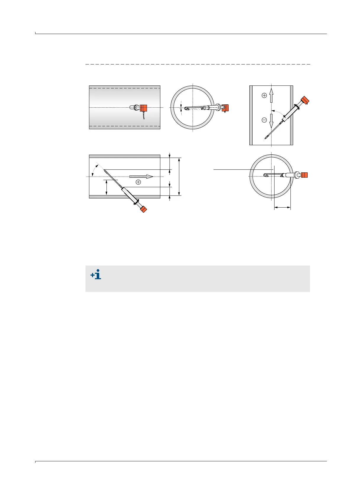
Fig. 29 Installing the sender/receiver unit type FLSE100-PR
Sender/receiver units with special lengths can be delivered if the condition for x with
standard nominal lengths cannot be observed.
Preventing condensate accumulations
If standard sender/receiver units are installed in vertical ducts, wet gases can cause
condensate to accumulate in the flange tube of sender/receiver unit A (
p. 15, Fig. 4). The
following onsite solutions can help prevent measuring problems (malfunctions caused by
structure-borne noise, see Service Manual), or damage when removing the sender/
receiver unit (condensate runs out):
● Completely insulating the flange with tube (reduces temperatures on the flange with
tube below the dew point)
● Draining continuous or periodical condensate through an opening (if necessary close-
able) at the deepest point of the flange tube (e.g. hole Ø 4 mm with plug:
Fig. 30) (only
when the condensate cannot damage the system or the environment)
● Returning the condensate to the duct through a hose connection between flange tube
and duct (
Fig. 30).
Horizontal duct
Di
45°
a
45°
1 ... 2°
b
x
x
Middle of trans-
ducer - transducer
distance
x = representative wall clearance at which the local gas flow rate is the same as the mean
velocity in the duct cross-section
Di = 0.35 ... 0.8 m:
a = b
Di > 0.8 m:
x 0.242 · Di /2
(accord. to ISO DIS
7145)
Vertical duct
In vertical ducts, a negative sign is shown on the LC-Display of the control unit
when the flow direction is from top to bottom. To change the displayed values
to positive values, enter a negative linear regression coefficient (
p. 144, 4.3).