10 FLOWSIC600 · Technical Information · 8010125 V 4.0 · © SICK AG
Important Information
Subject to change without notice
1.1 About this document
This manual describes the FLOWSIC600 measuring system, which is used to determine
the volumetric flow rate, volume and speed of sound in gases transported in pipelines. It
provides general information on the measuring method employed, design and function of
the entire system and its components, on planning, assembly, installation, calibration com
-
missioning, maintenance and troubleshooting. A detailed description of the various system
capabilities, options and settings which will assist in optimizing the meter configuration for
a specific application is also included.
This manual covers standard applications which conform with the technical data specified.
Additional information and assistance for special applications are available from your SICK
representative. However, it is generally recommended that advantage be taken of qualified
consulting services provided by SICK experts for your specific application.
This manual is a part of the FLOWSIC600 device documentation.
Documentation available via www.FLOWSIC600.com or from your local representative:
● FLOWSIC600 MODBUS specification document
● FLOWSIC600 HARTbus specification document
● FLOWSIC600 Technical Bulletin ENCODER Output
Documentation available from your local representative after training:
● FLOWSIC600 service manual
● FLOWSIC600 extraction tool operating instructions
1.2 Scope of document
The following terms will be used for measurands:
This document applies to meters with firmware version 3.6.00 or higher and
extended memory for the storage of e.g. hourly and daily mean values.
The software description in this document applies to MEPAFLOW600 CBM
V1.3.00.
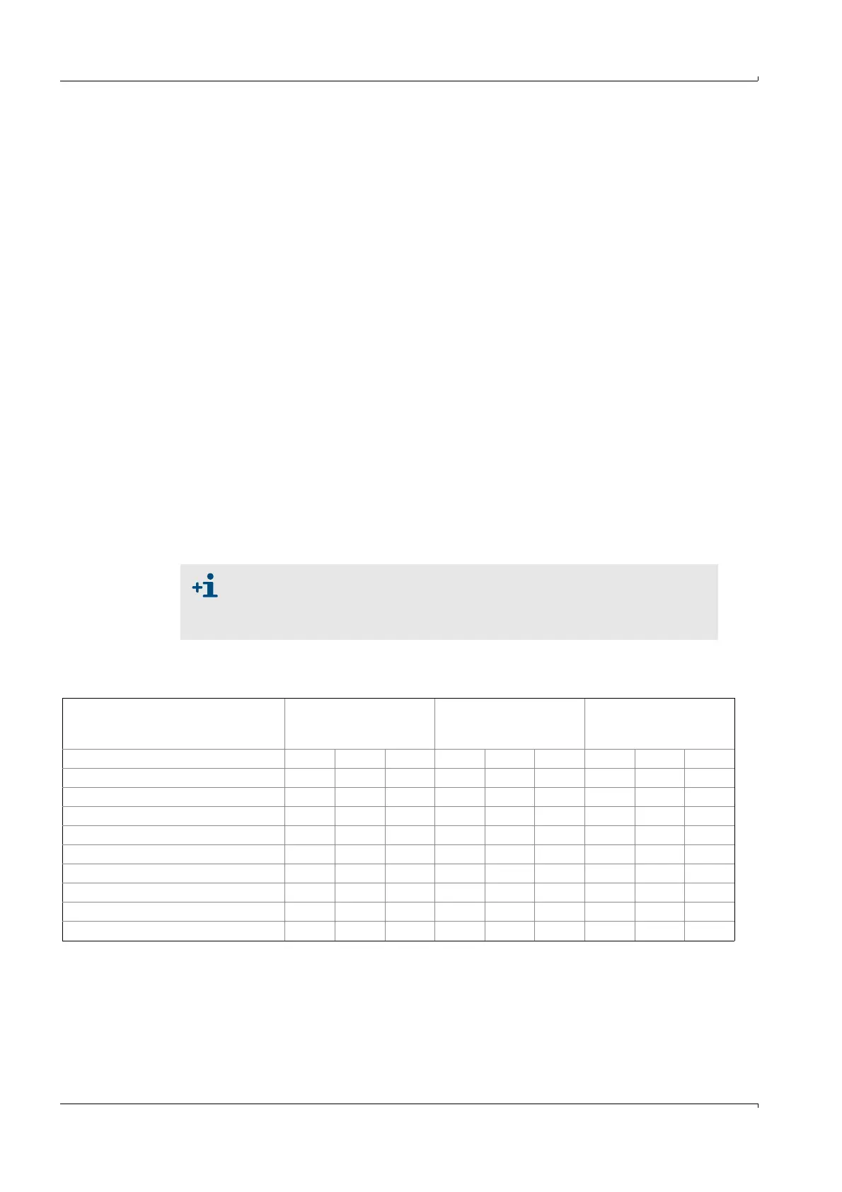
Measurand
Basic abbreviations
and units for
FLOWSIC600
Abbreviations used for
LCD-Display of SPU
MEPAFLOW600 CBM
software
Volume at flowing conditions Vf m³ acf Vf m³ cf Vf m³ acf
Volume at base conditions Vb Nm³ scf Vb m³ cf Vb Nm³ scf
Error volume at flowing conditions Ef m³ acf Ef m³ cf Ef m³ acf
Error volume at base conditions Eb Nm³ scf Eb m³ cf Eb Nm³ scf
Total volume at flowing conditions Vo m³ acf Vo m³ cf Vo m³ acf
Volume flow at flowing conditions Qf m³/h acf/h Qf m³/h cf/h Qf m³/h acfh
Volume flow at base conditions Qb Nm³/h scf/h Qb m³/h cf/h Qb Nm³/h scfh
Mass counter MtlbsMtlbsMtlbs
Error Mass Me t lbs M t lbs M t lbs
Mass flow at base conditions Mf t/h lbs/h M t/h lbs/h M t/h lbs/h

 Loading...


