108 FLOWSIC600 · Technical Information · 8010125 V 4.0 · © SICK AG
Installation
Subject to change without notice
4.4.4 Terminal enclosure on the SPU
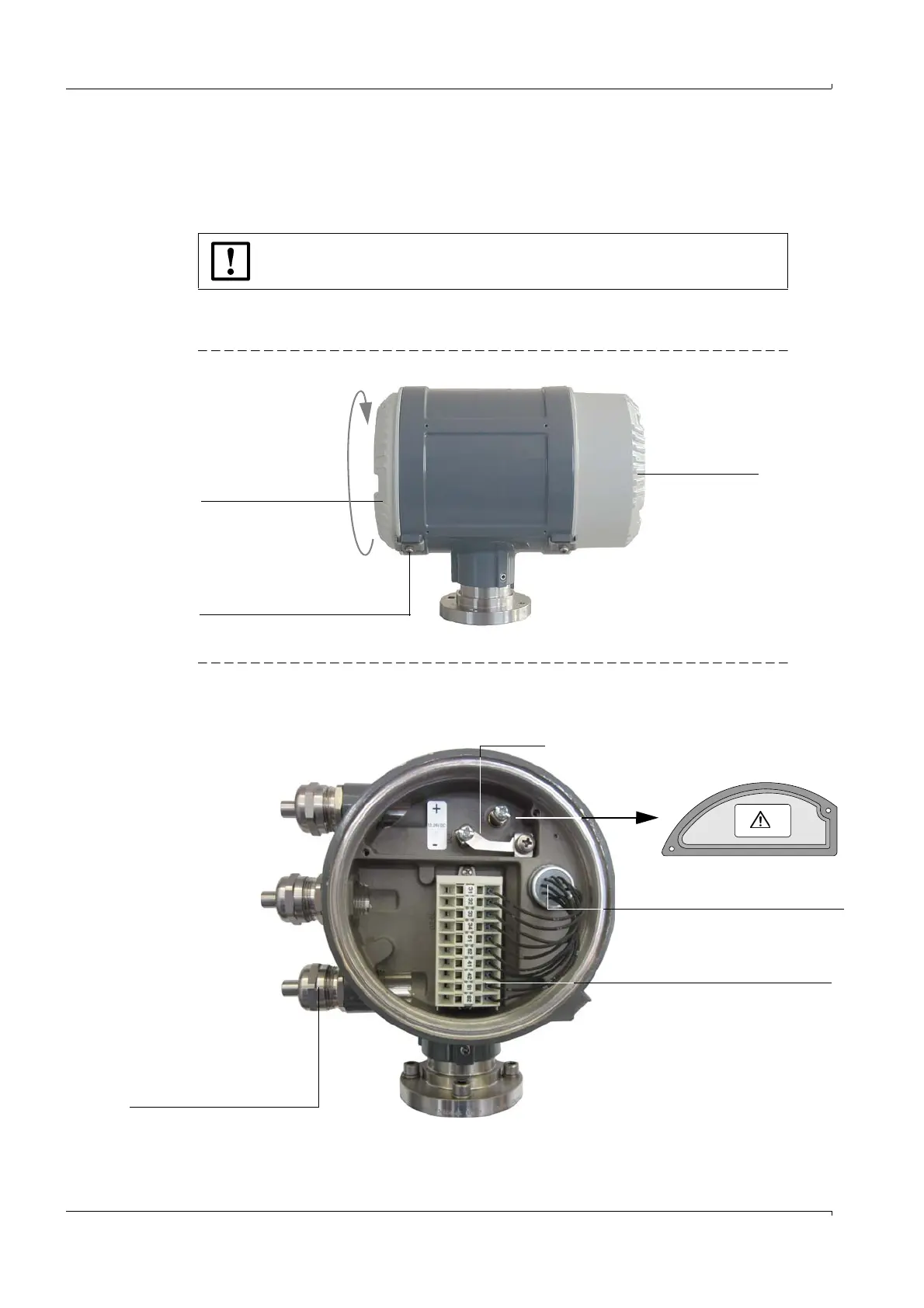
Opening the rear housing cover
Loosen the securing clip using a 3 mm Allen key.
Turn the rear housing cover counter-clockwise and take it off.
A schematic wiring diagram is provided on the inside of the rear housing cover (see also
pg. 238, 9.5).
Figure 49 SPU housing
Figure 50 Terminal box on the rear of the SPU (see Section
4.4.2 for North American wiring specification equivalents)
NOTICE: Lubricant
Only use LOCTITE 8156 as lubricant for front and rear housing cover.
Open the cover
Rear cover
Securing clip
Window cover
Bridge
Cover for power
supply terminals
Cable feed for internal 10-core
cable
10-pole terminal block
for signal inputs and outputs
1
2
HSK M type cable glands
M 20 x 1.5 (EU)
or ½ in NPT (North America)
Power supply
2 x 1.5 mm
2
(LiYCY or equivalent)
Digital output / current
output
4 x 2 x 0.5 mm
2
(Li2YCY [TP] or equivalent)
MODBUS
4 x 2 x 0.5 mm
2
(Li2YCY [TP] or equivalent)

 Loading...


