106 FLOWSIC600 · Technical Information · 8010125 V 4.0 · © SICK AG
Installation
Subject to change without notice
4.4.2 Cable specifications
Power supply 12 … 28.8 V DC
Digital output / current output
Serial port (RS485)
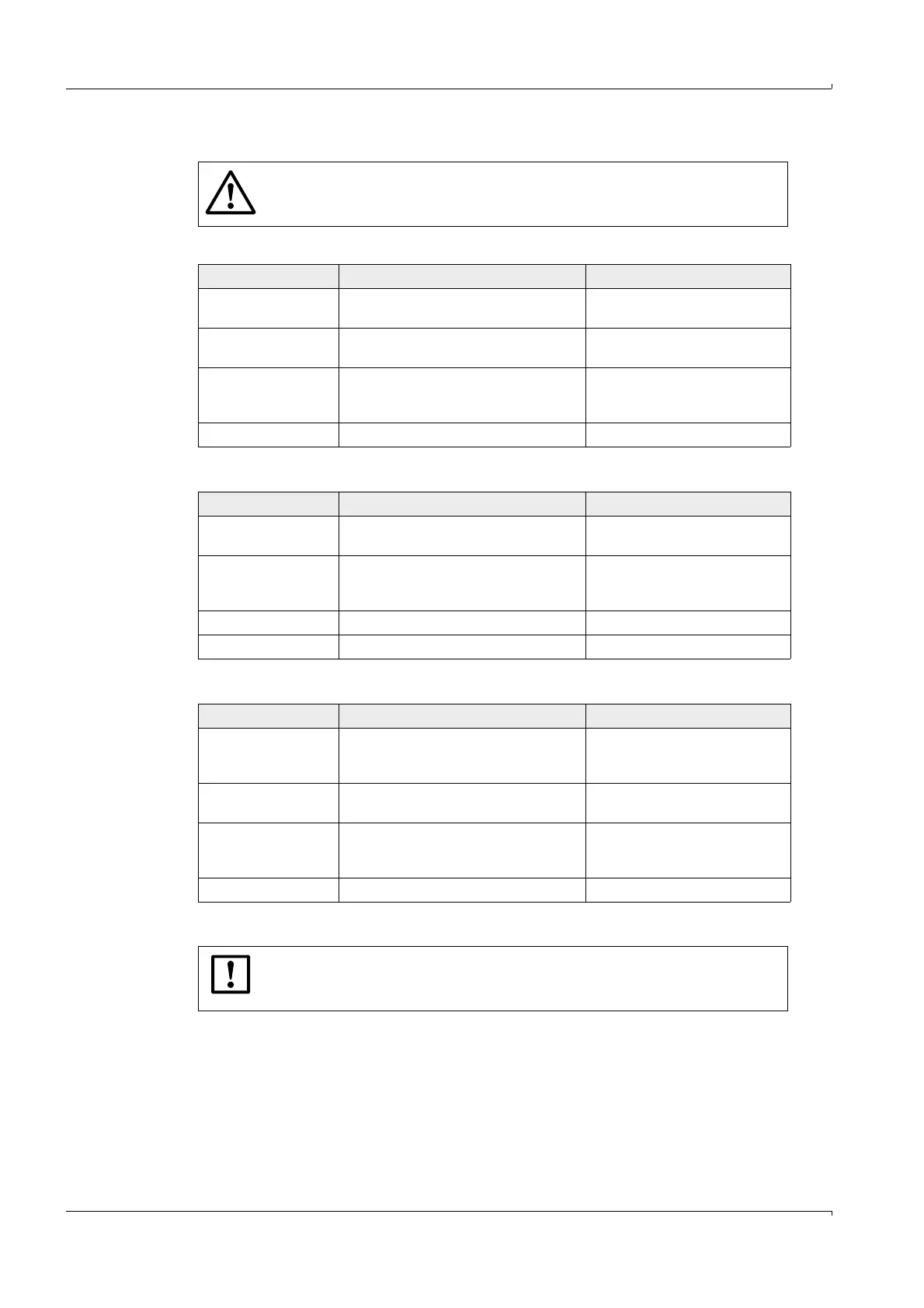
WARNING:
The cables must fulfil the requirements for use in hazardous areas (e.g. set
forth in EN /IEC 60079-14 or other relevant standards).
Specification Notes
Type of cable Two conductors Connect shielding (if present) to
ground terminal
Min./ max. cross-sec-
tional area
0.5 mm² / 2.5 mm² (20 - 12 AWG)
Maximum cable length Depending on loop resistance;
Minimum input voltage on the
FLOWSIC600 must be 12 V DC.
Peak current 150 mA
Cable diameter 6 ... 12 mm (1/4 to 1/2 inch) Fixing range of the cable glands
Specification Notes
Type of cable Twisted pair, shielded Connect shielding at other end to
ground terminal
Min./ max. cross-sec-
tional area
2 x 0.5/1 mm
2
(2 x 20-18 AWG) Do not connect unused conductor
pairs and prevent them from
accidental short-circuit
Maximum cable length Loop resistance 250
Cable diameter 6 ... 12 mm (1/4 to 1/2 inch) Fixing range of the cable glands
Specification Notes
Type of cable Twisted pair, shielded,
impedance approx. 100…150
low cable capacitance:
100 pF/m
Connect shielding at other end to
ground terminal
Min./ max. cross-sec-
tional area
2 x 0.5/1 mm
2
(2 x 20-18 AWG)
Maximum cable length 300 m at 0.5 mm² (1600 ft for 20 AWG)
500 m at 0,75 mm² (3300 ft for 20 AWG)
Do not connect unused conductor
pairs and prevent them from
accidental short-circuit
Cable diameter 6 ... 12 mm (1/4 to 1/2 inch) Fixing range of the cable glands
NOTICE:
Only the lower fault current may be used with an internally fed analog output
and use of HART communication.
 Loading...


