Product Description
FLOWSIC600 · Technical Information · 8010125 V 4.0 · © SICK AG 21
Subject to change without notice
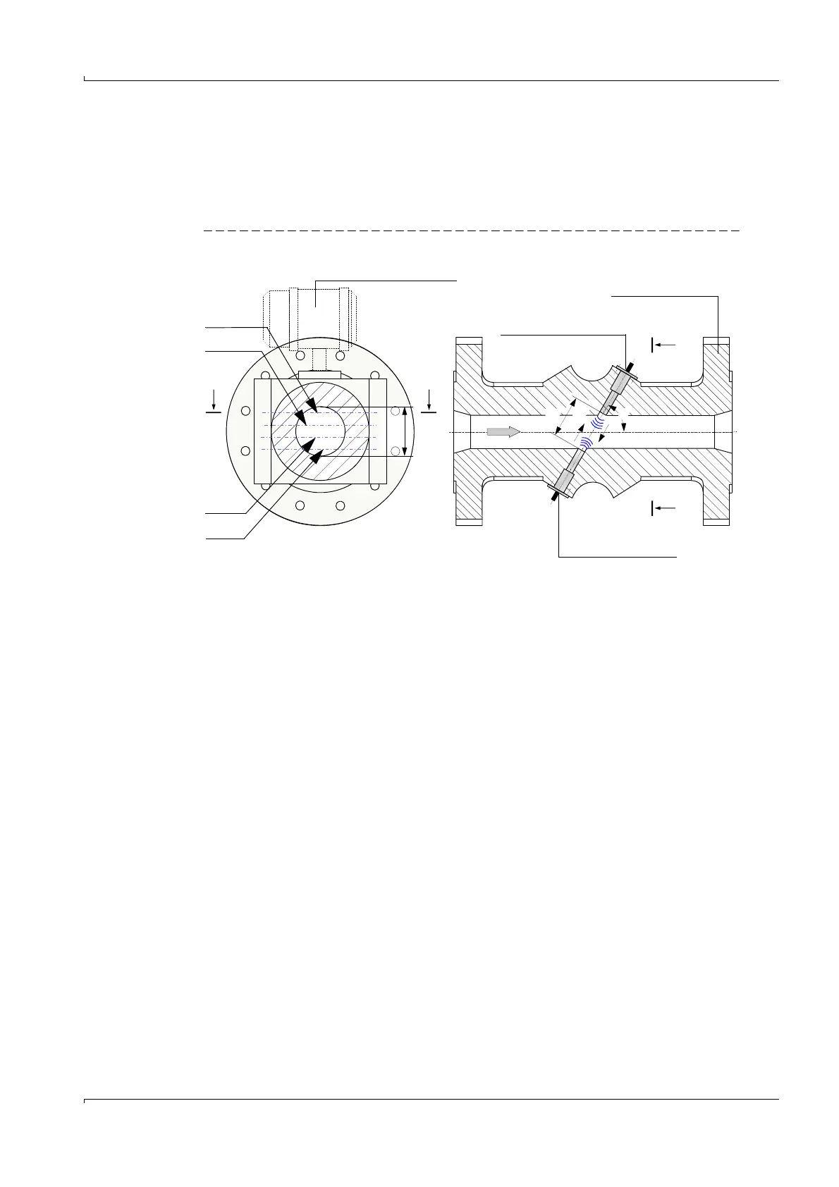
2.3 Measuring principle
The FLOWSIC600 operates by measuring the propagation delay of an ultrasonic pulse. The
standard 4-path meter is equipped with four pairs of identical ultrasonic transducers. The
transducer pairs are integrated in a meter body and arranged opposite one another at a
defined angle to the flow axis, thereby forming a direct measuring path (
Figure 7)
Figure 7 FLOWSIC600 measuring principle
The ultrasonic pulses cross the meter body from transducer to transducer. With no gas
flowing, the pulses are emitted with the same speed (speed of sound) in both directions.
When a gas is flowing through the meter body, the pulse in the direction of the gas flow is
faster, while the pulse flowing against the flow is slower. This means that the transit time is
shorter in the direction of flow (t
AB
) and longer against the direction of flow (t
BA
).
The ultrasonic transducers operate alternately as a transmitter and receiver. Each trans-
ducer is a piezoceramic element that is coupled with a diaphragm. To transmit signals, an
alternating current is applied to the piezoceramic element so that it vibrates mechanically
(piezoelectric effect). These vibrations are then transferred through the diaphragm to the
gas. The vibrations are propagated as acoustic waves in the gas and strike the diaphragm
on the opposite transducer after a propagation time that depends on the speed of sound
and on the gas velocity. The waves are transferred to the piezoceramic element in the form
of mechanical vibrations. They are then converted into an electrical signal by the inverse
piezoelectric effect and used for further signal analysis.
The signals are then processed to calculate the transit times of the acoustic signals
through the flowing medium. From the transit time the measurands can be calculated.
Ultrasonic transducer A
Ultrasonic transducer B
t
BA
Flow
D
Meter body
A
A
A - A
Signal processing unit (SCU)
Path 1
Path 3
B
B
B - B
Path 1
(standard mounting position)
L
t
AB
Path 2
Path 4
 Loading...


