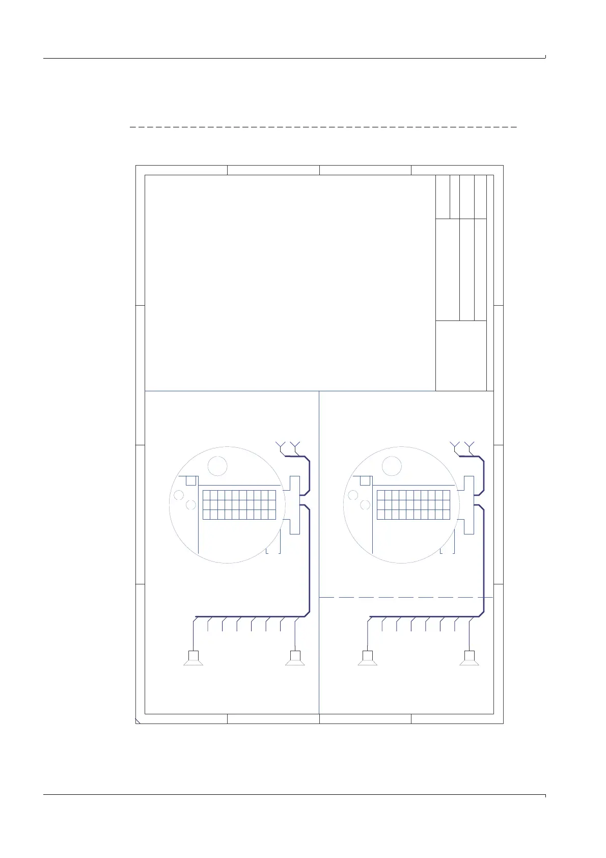
Up to 8 [Exia] Terminals
for Ultrasonic Transducers
manufactured by SICK only
with the following
Entity Parameters
Class I, Division 1, Groups B, C and D, Temp. Code T4, Class I, Division 2, Groups A, B, C and D, Temp. Code T4
Class I, Zone 1, Group II B + Hydrogene, Temp. Code T4, Class I, Zone 2, Group II C, Temp. Code T4
US-Transducer
US-Transducer
Up to 8 [Exia] Terminals
for Ultrasonic Transducers
manufactured by SICK only
with the following
Entity Parameters
Class I, Zone 0,
Group II B + Hydrogene,
Temp. Code T4
Class I, Zone 1, Group II B + Hydrogene, Temp. Code T4
Division 1 / Zone 0 / Zone 1 installation
1. Maximum non-hazardous area voltage not to exeed 125V
2. In the US install in accordance with the NEC (ANSI/NFPA 70) and
ANSI/ISA RP 12.6.)
3. In Canada install in accordance with the CEC part 1
4. [ Exia] is defined as Associated Equipment
5. WARNING: Substitution of components may impair Intrinsic Safety.
6. For Entity Installation, use CSA certified safety barriers or other
CSA certified Associated Equipment that satifies the following
condtions:
Voc <= Vmax, Isc <= Imax., Ca >= Ci + Ccable, La >= Li + Lcable.
See drawing no. 781.00.02 page 4 for Entity parameters
Division 2 / Zone 2 installation
1. Install in accordance with the CEC or NEC.
2. WARNING: Explosion Hazrad - Do not disconnect equipment unless power
has been switched off or the area is known to be non - hazardous.
3. WARNING: Explosion Hazard - Substition may impair suitability for
Class 1, Division 2
Voc=38.9V
Isc=59mA
Ca=3.4nF
La=0.03mH
Voc=38.9V
Isc=59mA
Ca=3.4nF
La=0.03mH
Power Supply: Terminals 1(+), 2(-)
Vin=12V to 24V
Iin= 60mA to 150mA
Current output 4-20mA: Terminals 31,32
Vin=30V
Iin=100mA
Binary outputs 1, 2 and 3
Pulse output: Terminals 51, 52
Config. output: Terminals 41, 42
Error output: Terminals 81, 82
Vin= 30V
Iin= 100mA
Data-Interface (RS485): Terminals 33, 34
Vin=5V
Iin=174mA
Divsion 1 / Zone 1 Explosion Proof installation
Connector
Connector
SPU-LINK
(Option only)
Voc=12.3V
Isc=130mA
Ca=600nF
La=1mH
Connector
Connector
SPU-LINK
(Option only)
Voc=12.3V
Isc=130mA
Ca=600nF

 Loading...


