Installation
FLOWSIC600 · Technical Information · 8010125 V 4.0 · © SICK AG 99
Subject to change without notice
4.2.2 Installation configurations
The choice of the installation configuration (see
Figure 45 and
Figure 46) depends on
type and extent of the flow disturbance at the installation position.
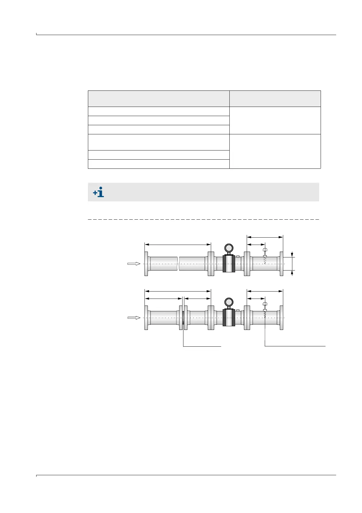
Unidirectional use
Figure 45 FLOWSIC600 installation in the pipeline for unidirectional use
Type of disturbance (distance upstream < 20 DN)
Possible installation
configuration
None
Configuration 1 or 2Elbow, reducer
Double elbow out of plane, T piece
Gas pressure controller with/ without noise
abatement trim
Configuration 2
Diffuser
Diffuser with swirling flow
When configuration 2 (with flow conditioner) is used, the velocity of gas must
not exceed 40 m/s (131 ft/s) in the pipe.
3 DN
min. 2 DN min. 3 DN 1.5 .. 5 DN
Flow conditioner Temperature measuring port
Configuration 1
Configuration 2
10 DN 1.5 .. 5 DN
FLOWSIC600 3 DN
DN
5 DN
 Loading...


