Installation
FLOWSIC600 · Technical Information · 8010125 V 4.0 · © SICK AG 109
Subject to change without notice
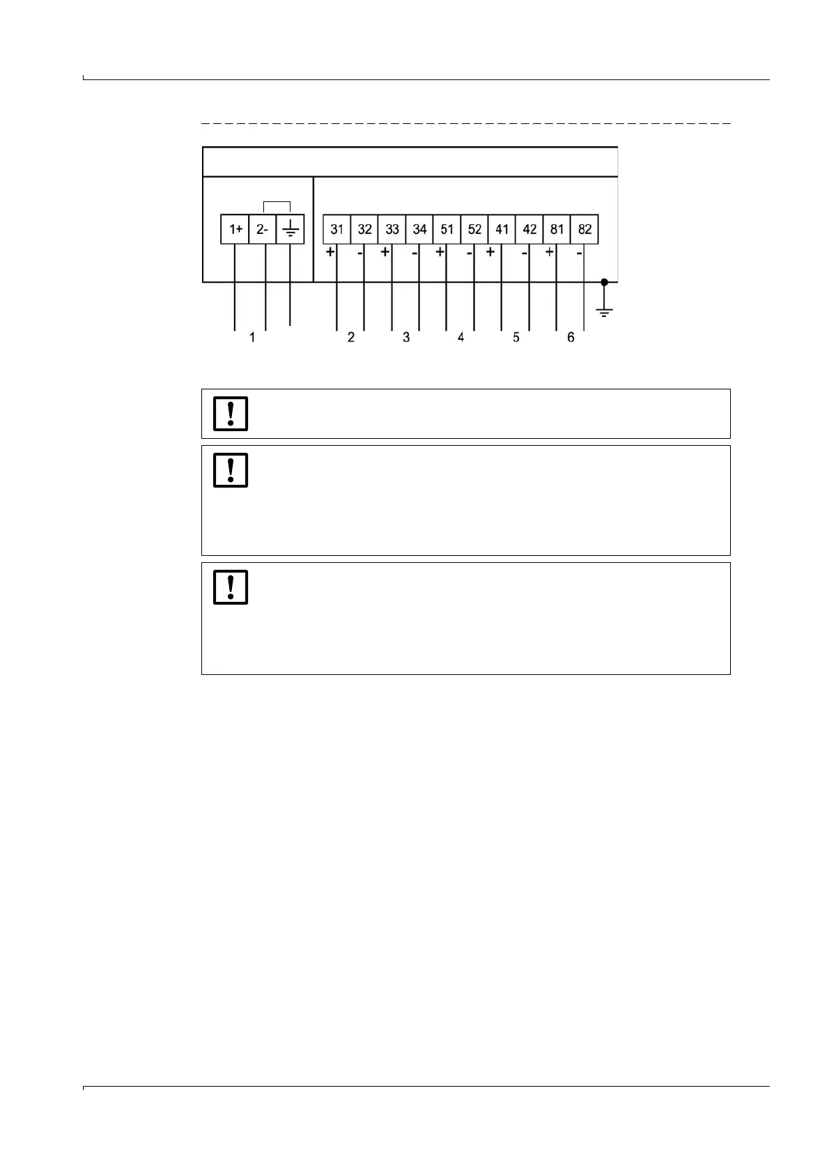
Figure 51 Terminal assignment for use in safe areas
Terminal box
Power supply Field connections (10-pole terminal block)
PE
PE
NOTICE: Potential equalization
PE: Potential Equalization terminal must be connected to earth ground.
NOTICE: Device-internal bridge
Terminals 2 and PE are bridged internally, i.e. there is no insulation between PE
and negative potential (
Figure 50).
This bridge is a firm part of the device and mandatory. It must not be
removed or altered.
Altering the bridge voids the manufacturer's warranty.
NOTICE: Termination of Modbus lines
Begin and end of the Modbus lines must be terminated.
● Terminal 81/82: Always terminated
● Terminal 33/34: Switchable, terminated ex factory
For detailed information, see Service Manual FLOWSIC600, Section 4.4 "Serial
interface RS485".

 Loading...


