140 FLOWSIC600 · Technical Information · 8010125 V 4.0 · © SICK AG
Commissioning
Subject to change without notice
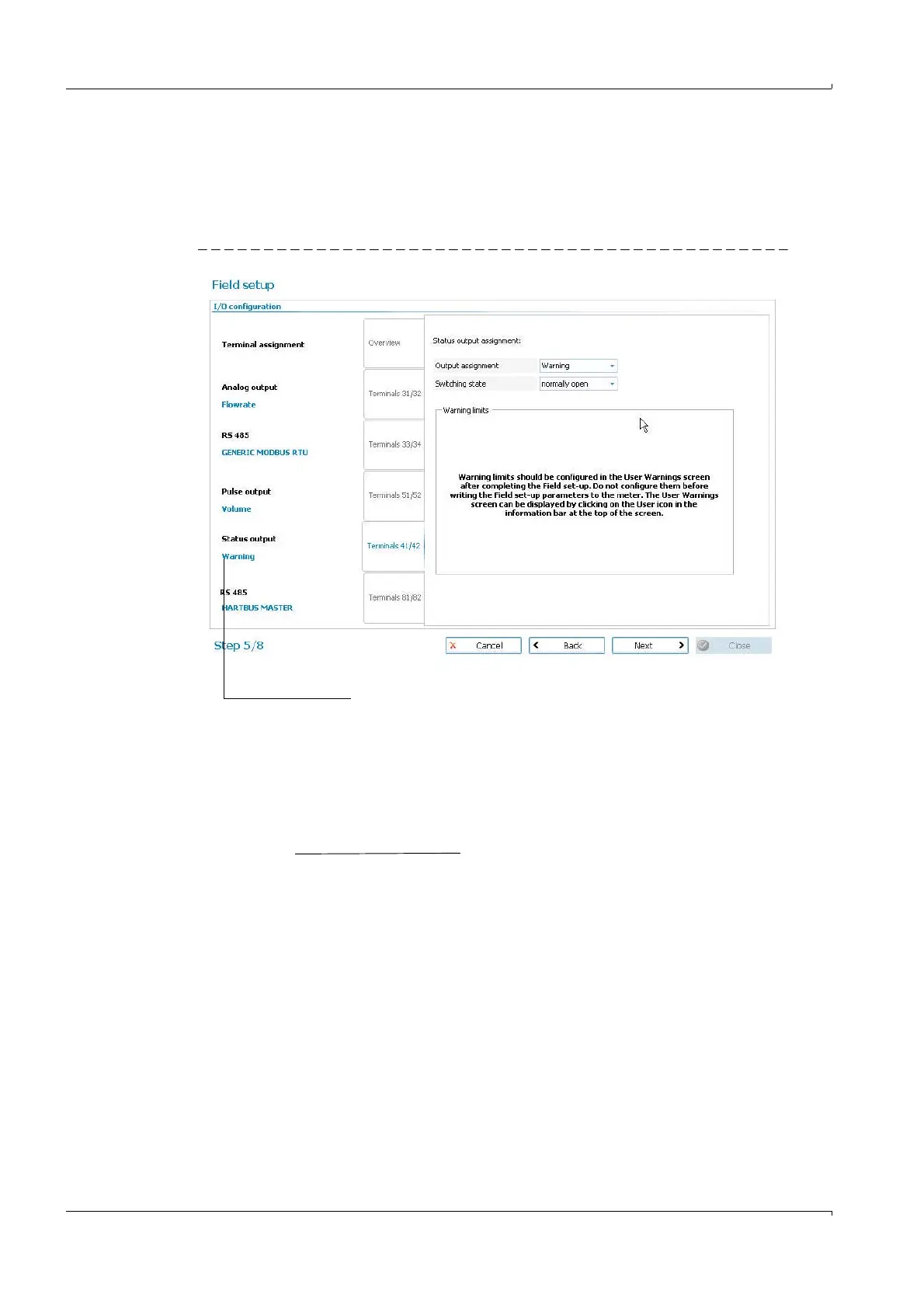
Warning limits
If a status output was configured as "Warning" output in Step 4 (
pg. 138, 5.5.5), clicking on
the tab for this output will display the settings for the switching state.
The User Warning Limits can be configured and activated after the completion of the Field
Setup Wizard (
pg. 149, 5.7.1).
Figure 68 Status output, configured for "Warning"
Analog output
To adapt the FLOWSIC600 to the different application conditions the analog output has to
be configured. The adjustment of the analog output requires the change of various param
-
eters.
The output current I
out
is calculated as follows:
I
out
= 4 mA + 16 mA
Output configured as
warning output
Q:
Actual volume flow rate (other possible sources: normalized
volume flow rate, mass flow rate, molar mass)
AORangeHigh: Upper range limit (has to be set)
AORangeLow: Lower range limit (has to be set)
Q AORangeLow
(AORangeHigh - AORangeLow)

 Loading...


