142 FLOWSIC600 · Technical Information · 8010125 V 4.0 · © SICK AG
Commissioning
Subject to change without notice
See
pg. 221, 9.3 for more information on the LCD display.
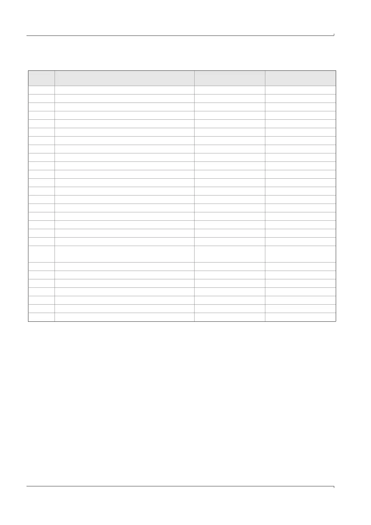
Table 19 Possible sources for lines on LCD
Reg. # Measurement output
Abbreviation in
MEPAFLOW600 CBM
Abbreviations on LCD
7002 Volume flow at base conditions
1
Qb +/- Qb
7001 Volume flow at flowing conditions
1
Qf +/- Qf
5010 Volume counter forward
1
V forward + Vf
5012 Volume counter reverse
1
V reverse - Vf
5011 Error volume counter forward
1
E forward + Ef
5013 Error volume counter reverse
1
E reverse - Ef
7004 Velocity of gas VOG VOG
7003 Speed of sound SOS SOS
7022 Pressure (from external source) p p
7021 Temperature (from external source) T T
3029 Frequency FO FO
7035 Analog output AO AO
3020 Input Voltage Uin Uin
5016 Forward Volume Total
1
Vfo forward + Vo
5018 Reverse Volume Total
1
Vfo reverse - Vo
5041 Volume at base conditions forward
1
Vb forward + Vb
5043 Volume at base conditions reverse
1
Vb reverse - Vb
5042 Error volume at base conditions forward
1
Eb forward + Eb
5044 Error volume at base conditions reverse
1
Eb reverse - Eb
5045
Total volume at flowing conditions
(plus forward, minus reverse volume)
1
Vo Vo
5079 Total mass counter forward
1
M forward + M
5081 Total mass counter reverse
1
M reverse - M
7047 Mass flow M flow +/- Mf
5085 Total volume at base conditions forward
1
Vo forward + VB
5047 Total volume at base conditions reverse
1
Vo reverse - VB
7065 Volume flow at base conditions as m
3
/d Qb (m
3
/d) +/- Qb
-None empty row -
1
The 18 digit total volume counter values are stored in two long word registers of 9 digits each. The first 9 digits are stored in the "low"digit register, and
the last 9 digits in the "high" digit register. The LCD displays only the"low" bits of the total volume counters.
 Loading...


