40 FLOWSIC600 · Technical Information · 8010125 V 4.0 · © SICK AG
Product Description
Subject to change without notice
*The "active" or "inactive" state can be assigned to the electric switch status "normally
open" or "normally closed" by configuration in the MEPAFLOW600 CBM software (adjust
settings for Reg. #5101 on the "Parameters" page
pg. 137, 5.5.4.).
The output signal designation is described in the Technical Information
2.5.1, p.32.
The LCD display can display measured values, parameters, messages and other informa-
tion (see
pg. 214, 9.2).
A flashing letter in the upper right corner of the LCD display indicates that a logbook con-
tains unacknowledged logbook entries. Depending on the type of entry this will be:
● "I" for Information
● "W" for Warning
● "E" for Error
After acknowledging all new entries, the letter stops flashing. For details see
pg. 176,
6.4.1.
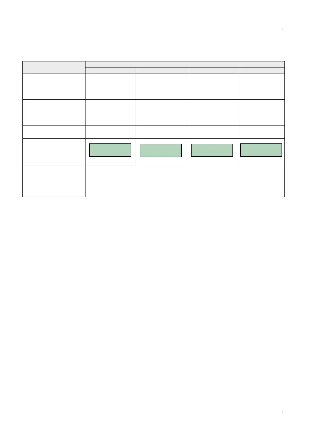
Table 7 Status output
Output signal / LCD / port
Signal behavior
Measurement status Check request status Configuration Mode Data invalid
"Check request"
Status signal
Status
"active / inactive" *
Measurement valid
Status
"active / inactive" *
Compensation of
path failure
"undefined" "undefined"
"Direction of flow"
Status signal
Status
"active / inactive" *
Positive or negative
direction of flow
Status
"active / inactive" *
Positive or negative
direction of flow
"undefined" "undefined"
"Warning"
Status
"active / inactive" *
Status
"active / inactive" *
"undefined" "undefined"
LCD display
Display flashing Display flashing
Serial port RS485
● Measured value, diagnosis information and parameters
● Measuring data logging, diagnosis and configuration through the MEPAFLOW600
CBM software
● Connection with external process control equipment through implemented MODBUS
protocol (data polling)
+V 123456 m³
-V 1234 m³
1234 m³ E
FLOWSIC600
Configuration
+V 123456 m³ E
-V 1234 m³

 Loading...


