Chapter 12 Operating instructions
S300
126 © SICK AG • Industrial Safety Systems • Germany • All rights reserved 8010948/YY96/2016-02-17
Subject to change without notice
Technical specifications
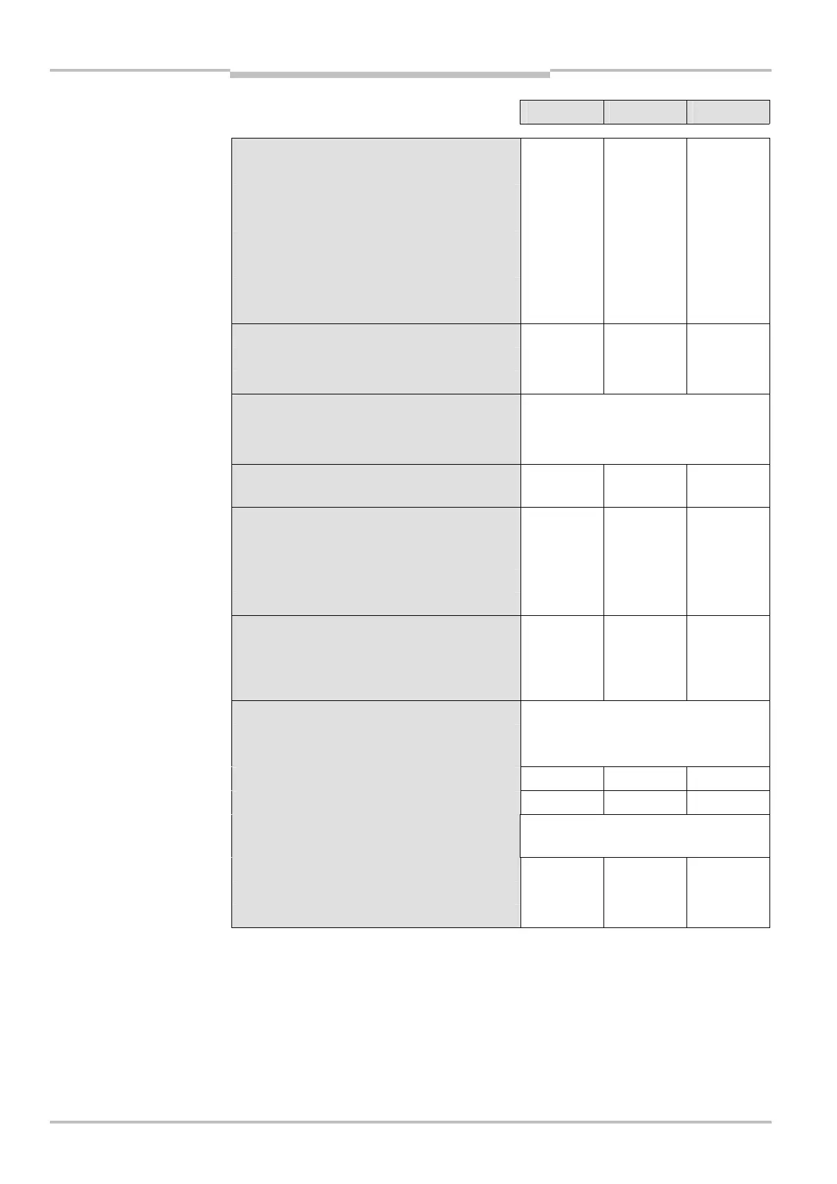
Minimum Typical Maximum
Dynamic control inputs
Input resistance when HIGH 2 kc
Voltage for HIGH 11 V 24 V 30 V
Voltage for LOW –3 V 0 V 5 V
I
nput capacitance 1 nF
Static input current 6 mA 15 mA
Duty cycle (Ti/T) 0.5
Input frequency 100 kHz
Voltage supply for incremental encoders
24 V voltage output V
S
– 3 V V
S
Current load per incremental encoder 50 mA 100 mA
Velocity range that can be sampled
Forward
Backward
From +10 cm/s to +2000 cm/s
From –10 cm/s to –2000 cm/s
Velocity tolerance with same direction
information
45%
Tolerance time for exceeding velocity with
same direction information from the
incremental encoders
at < 30 cm/s 60 s
at M 30 cm/s 20 s
Tolerance time for different direction
information or signal failure from an
incremental encoder
at > 10 cm/s
0.4 s
Incremental encoders that can be evaluated
Type Two-channel rotary encoder with 90°
phase offset
Enclosure rating IP 54
Supply voltage V
S
– 3 V V
S
Outputs required on the incremental
encoders
Push/pull
Pulse frequency 100 kHz
Number of pulses per cm 50
Cable length (screened) 10 m