Chapter 7 Operating instructions
S300
88 © SICK AG • Industrial Safety Systems • Germany • All rights reserved 8010948/YY96/2016-02-17
Subject to change without notice
Application examples and
connection diagrams
7 Application examples and connection diagrams
T
he examples shown are only provided as an aid for your planning. You may need to con-
sider additional protection measures for your application.
In the examples with protective field switching, note that at the time of the switching there
may already be a person in the protective field. Only by means of switching in the correct
t
ime frame (i.e. before the danger occurs at this point) is reliable protection provided (see
section 5.6 “Time for monitoring case switching” on page 71).
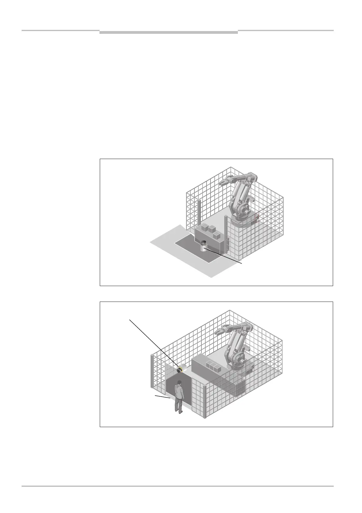
7.1 Stationary applications
7.1.1 Applications with one monitored area (S300 Standard)
The area is permanently monitored by the S300.
The access is monitored permanently. For safety against manipulation on the S300, e.g.
the floor is used as a reference. If the alignment of the S300 changes (e.g. due to changes
to the bracket), the S300 switches its OSSDs to the OFF state.
protection with
S300 Standard
with S300 Standard
protective field and warning field
— mounted horizontally
protective field — mounted
vertically