Chapter 7 Operating instructions
S300
92 © SICK AG • Industrial Safety Systems • Germany • All rights reserved 8010948/YY96/2016-02-17
Subject to change without notice
Application examples and
connection diagrams
7.3 Connection diagrams
Only use relays/contacts with positively guided contacts. The protection elements
connected in parallel with the relays/contactors are used for arc-suppression.
Ensure that there is adequate arc-suppression at the relays/contactors. Take into
account that arc-suppressors may lengthen the response time.
The arc-suppressors must be in parallel with the relays/contactors (not across the
contacts).
If you want to operate two safety laser scanners in a system (communication via EFI),
then the same earthing method must be used for both safety laser scanners.
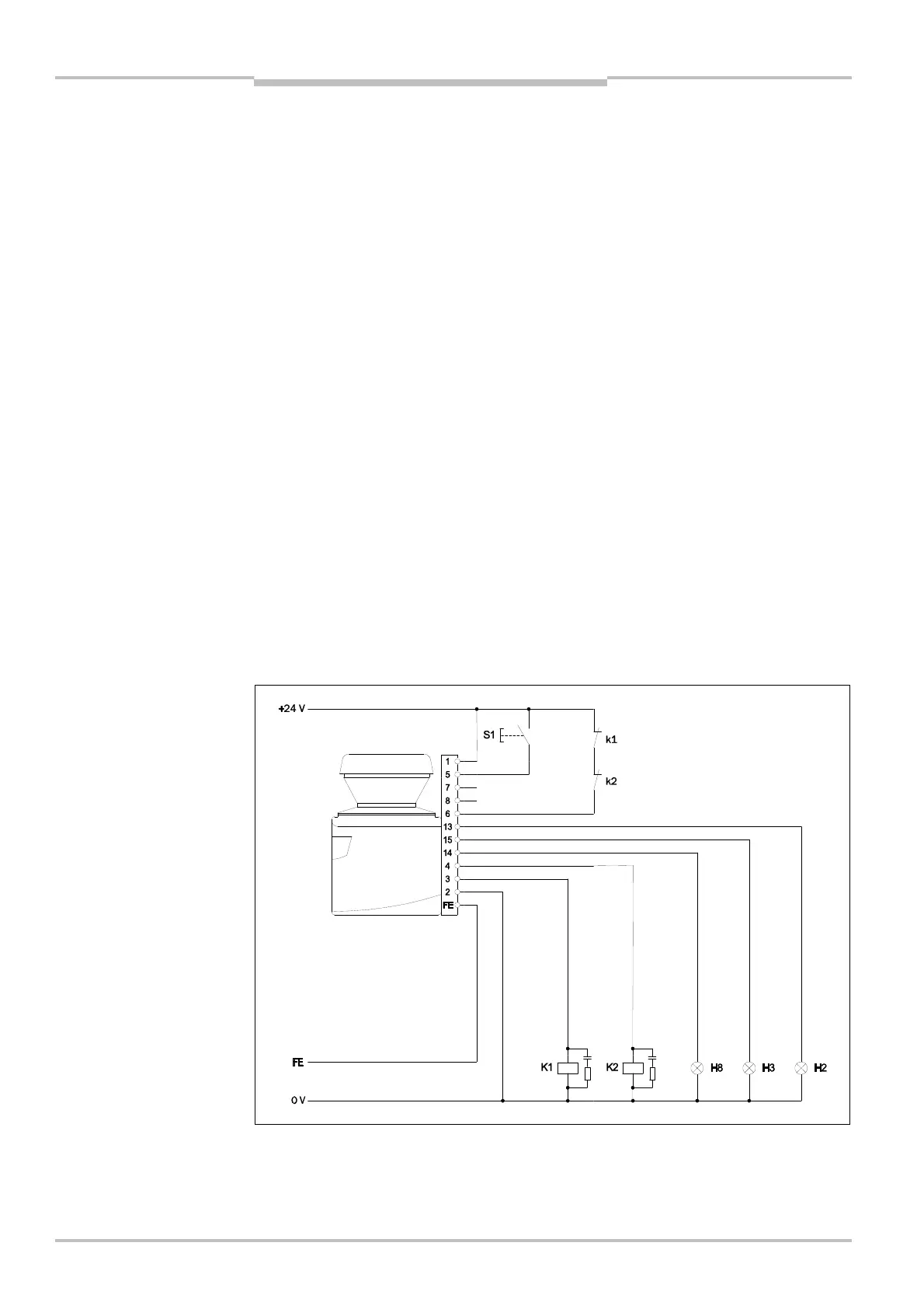
Sketch key
k1 and k2 or k3 and k4 = output circuits
These contacts are to be connected to the controller such that, with the output circuit
open, the dangerous state is disabled. For categories 3 and 4 according to
EN ISO 13849<1, the integration must be dual-channel (x/y paths). Observe the
maximum values for the loading of the outputs (see section 12.4 “Data sheet” on
page 120).
FE = functional earth
To achieve the specified EMC safety, the functional earth (FE) must be connected (e.g. to
the vehicle’s or system’s central earth star point).
H2 = sensor for Error/contamination
H3 = sensor for Reset required
H8 = sensor for Warning field interruption
7.3.1 Restart interlock and external device monitoring
S300 Standard in conjunction with relays/contactors; operating mode: with restart inter-
lock and external device monitoring.
Notes
for restart interlock and
external device monitoring
Standard