Chapter 3 Operating instructions
S300
24 © SICK AG • Industrial Safety Systems • Germany • All rights reserved 8010948/YY96/2016-02-17
Subject to change without notice
Product description
S300 Expert:
Protection of an automated
guided vehicle (AGV) with output
of processed measured data (as
navigation aid, e.g. during
docking maneuvers)
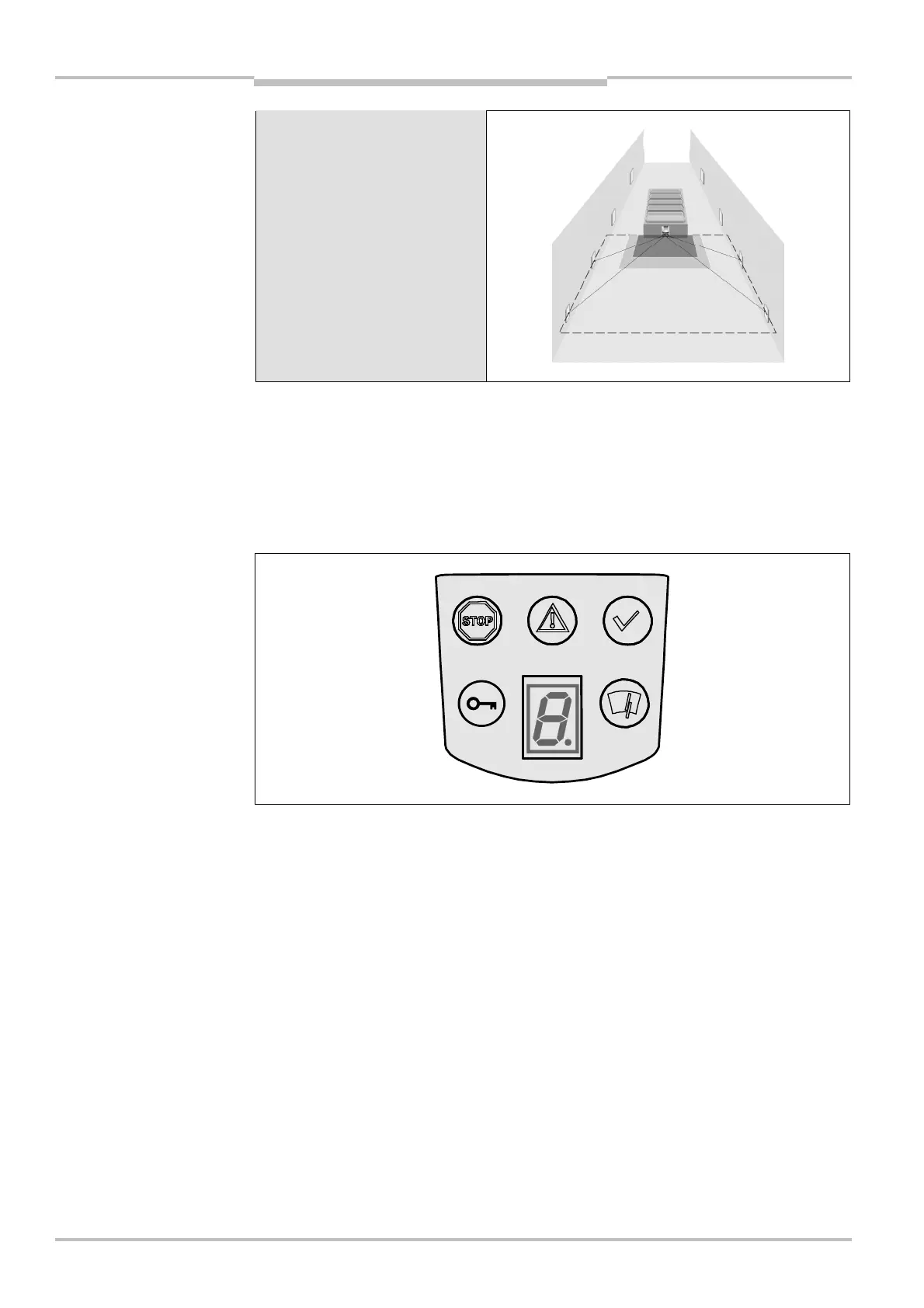
3.4 Status indicators
3.4.1 LEDs and 7@segment display
The LEDs and the 7<segment display indicate the operational status of the S300. They are
on the front face of the safety laser scanner.
The symbols have the following meaning:
OSSDs in the OFF state (e.g. in case of object in the protective field, monitored contour
changed, reset required, lock-out)
Warning field interrupted (object in warning field)
OSSDs in the ON state (no object in the protective field)
Reset required
Optics cover contaminated
7<segment display for the indication of the status and errors
You will find detailed information in section 11.3 “Error and status indications on the
LEDs” on page 108 and in section 11.4 “Error and status indications on the 7<segment
display” on page 110.
the S300
Note