Operating instructions Chapter 5
S300
8010948/YY96/2016-02-17 © SICK AG • Industrial Safety Systems • Germany • All rights reserved 73
Subject to change without notice
Mounting
5.7 Mounting steps
S
pecial features to note during mounting:
Mount the S300 such that it is protected from moisture, dirt and damage.
Ensure that the entire field of view of the S300 is not restricted.
Mount the safety laser scanner such that the indicators are easy to see.
Always mount the S300 so that there is still enough space for mounting and removing
the system plug.
Avoid excessive shock and vibration loading on the safety laser scanner.
On systems that suffer from heavy vibration, prevent the fixing screws from coming loose
using screw locking devices.
Regularly check the tightness of the fixing screws.
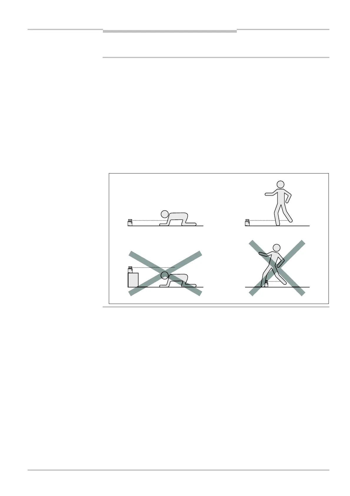
Prevent personnel from being able to crawl beneath, stand behind or climb over the
protective field by means of appropriate mounting of the S300.
The origin of the scan plane is 116 mm above the bottom edge of the S300 (see
section 12.6.3 “Scan plane origin” on page 134).
There are three possible ways of fixing the S300:
direct mounting without mounting kit
mounting with mounting kit 1a or 1b
mounting with mounting kit 2 (only in conjunction with mounting kit 1a or 1b)
You will find the part numbers for the mounting kits in section 13.3.1 “Mounting kits” on
page 135.
Pay attention to the maximum tightening torque of the M5 fixing screws on the S300 of
max. 5.9 Nm.
WARNING
beneath, standing behind,
climbing over
Note