Chapter 6 Operating instructions
S300
86 © SICK AG • Industrial Safety Systems • Germany • All rights reserved 8010948/YY96/2016-02-17
Subject to change without notice
Electrical installation
6.3 Pre-assembled system plugs
T
o connect the S300 variants, the following pre-assembled system plugs are available (see
also section 13.3.2 “System plug S300” on page 136):
For S300 Standard
SX0B-B1105G, SX0B-B1110G, SX0B-B1114G and SX0B-B1120G
– with 11 cores, unscreened (M16 cable gland)
– 5, 10, 14 or 20 m long
For S300 Professional and Expert with dynamic inputs
SX0B-B1105J and SX0B-B1110J
– with 11 cores, unscreened (M16 cable gland)
– 5 or 10 m long
– with 2 M12 cable glands (for incremental encoders), enclosed loose
For S300 Advanced, Professional and Expert with static inputs
SX0B-B1505G and SX0B-B1510G
– with 15 cores, unscreened (M16 cable gland)
– 5 or 10 m long
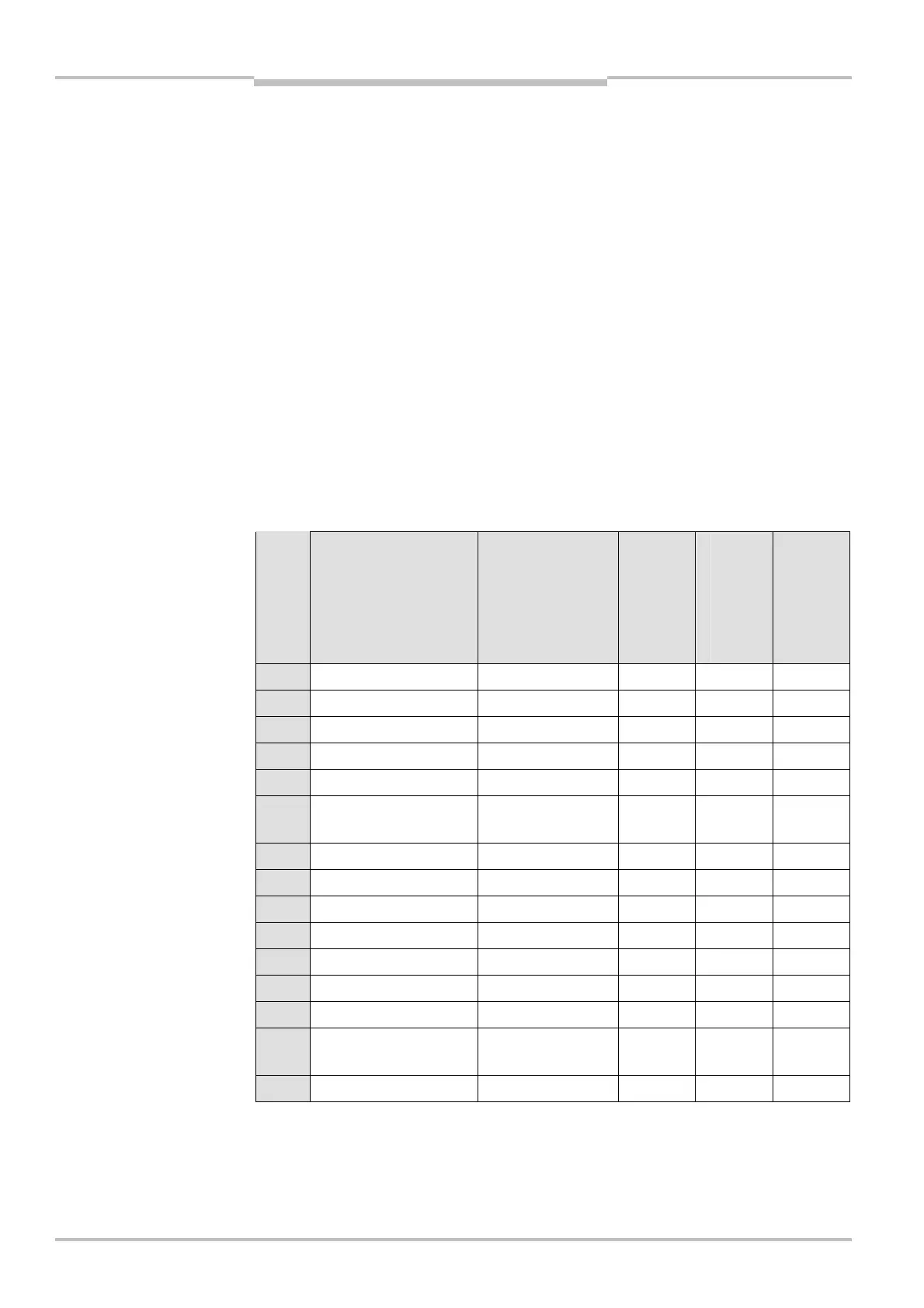
Pin Signal Wire color
SX0B-B1105G
SX0B-B1110G
SX0B-B1120G
SX0B-B1105J
SX0B-B1110J
SX0B-B1505G
SX0B-B1510G
FE Functional earth Green
1 +24 V DC Brown
2 0 V DC Blue
3 OSSD1 Gray
4 OSSD2 Pink
5 UNI<I/O1/RESET/
C1
Red
6 UNI<I/O2/EDM Yellow
7 A1 or INC1_0 White/blue
8 A2 or INC1_90 White/gray
9 B1 or INC2_0 White/purple
10 B2 or INC2_90 White
13 UNI<I/O3/ERR White/black
14 UNI<I/O4/WF White/brown
15 UNI<I/O5/
RES_REQ/C2
Red/blue
16 STBY White/green
pre6assembled system plug