Chapter 3 Operating instructions
S300
20 © SICK AG • Industrial Safety Systems • Germany • All rights reserved 8010948/YY96/2016-02-17
Subject to change without notice
Product description
3.3 S300 variants
3.3.1 Device components
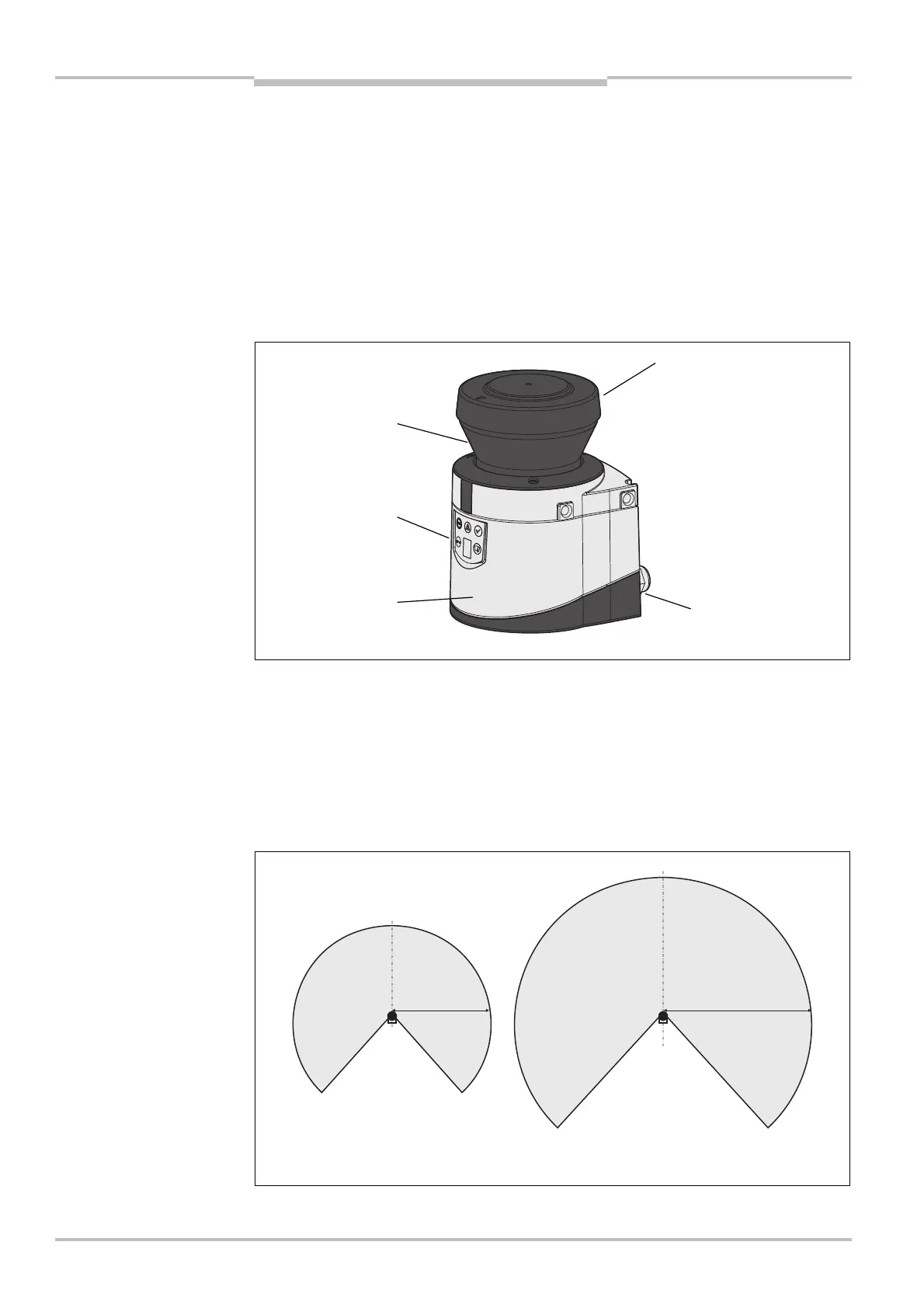
The S300 safety laser scanner comprises three components:
the sensor with the opto-electronic acquisition system, the LEDs and the 7<segment
display
the optics cover with the window for the light output
the system plug with the configuration memory (the system plug contains all electrical
connections with the exception of the configuration interface)
3.3.2 Functions of the S300 variants
So that different applications can be covered, four S300 variants each with two different
scanning ranges are available.
Scanning ranges
The S300 variants differ in the maximum scanning range and the resulting size of the
protective field.
76segment
light output