Operating instructions Chapter 7
S300
8010948/YY96/2016-02-17 © SICK AG • Industrial Safety Systems • Germany • All rights reserved 93
Subject to change without notice
Application examples and
connection diagrams
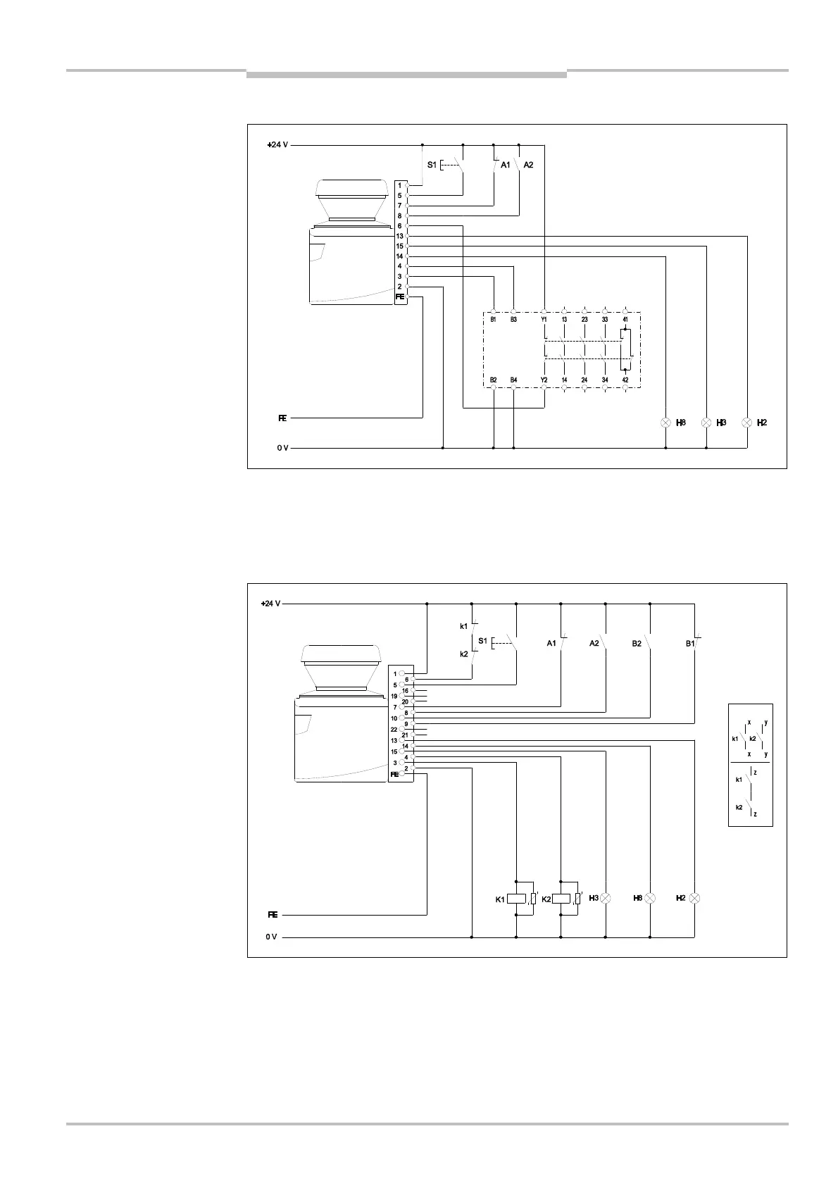
7.3.2 Protective field switching with a static input pair
S300 Advanced in conjunction with UE10<3OS; operating mode: with restart interlock and
external device monitoring; protective field switching by means of control input IN A. You
will find more detailed information in the data sheet on the UE10 series.
7.3.3 Protective field switching with two static input pairs
S300 Advanced in conjunction with relays/contactors; operating mode: with restart inter-
lock and external device monitoring; protective field switching by means of control inputs
IN A and IN B.
for protective field switching
with a static input pair
for protective field switching
using two static input pairs
Advanced
UE10-3OS
Advanced