Operating instructions Chapter 4
S300
8010948/YY96/2016-02-17 © SICK AG • Industrial Safety Systems • Germany • All rights reserved 35
Subject to change without notice
Configurable functions
4.4 Incremental encoder
T
he S300 Professional and the S300 Expert have two dual-channel dynamic control inputs
using which the possible monitoring cases can be switched as a function of the velocity.
For this purpose incremental encoders must be connected to the dynamic control inputs.
Per incremental encoder, one 0°/90° output is required so that the direction of travel can
be determined.
If you want to use the inputs A and B as dynamic control inputs, select the Indicate
velocity option.
4.4.1 Pulses per cm travel that are output by the incremental encoders
The result is dependent on the number of pulses the incremental encoder supplies per
revolution, and on the ratio between the wheel on the vehicle and the friction wheel on
which the incremental encoder is mounted.
How to calculate the number of pulses per centimeter:
Example:
The wheel on a forklift truck has a diameter of 35 cm.
The friction wheel on which the incremental encoder is mounted has a diameter of
3.5 cm.
The incremental encoder used supplies 1000 pulses per revolution.
Circumference of the forklift truck wheel = d × [ = 35 cm × [ = 109.96 cm
One revolution of the forklift truck wheel corresponds to ten revolutions of the friction
wheel and therefore 10,000 pulses from the incremental encoder.
For this information the number of pulses per centimeter of distance covered by the
vehicle is:
Pulses/cm = 10,000 : 109.96 = 90.94
On configuring the incremental encoder in the CDS, you must therefore enter the rounded
value “91” in Pulses per centimeter in the CDS. The user software calculates from this
value the maximum velocity allowed.
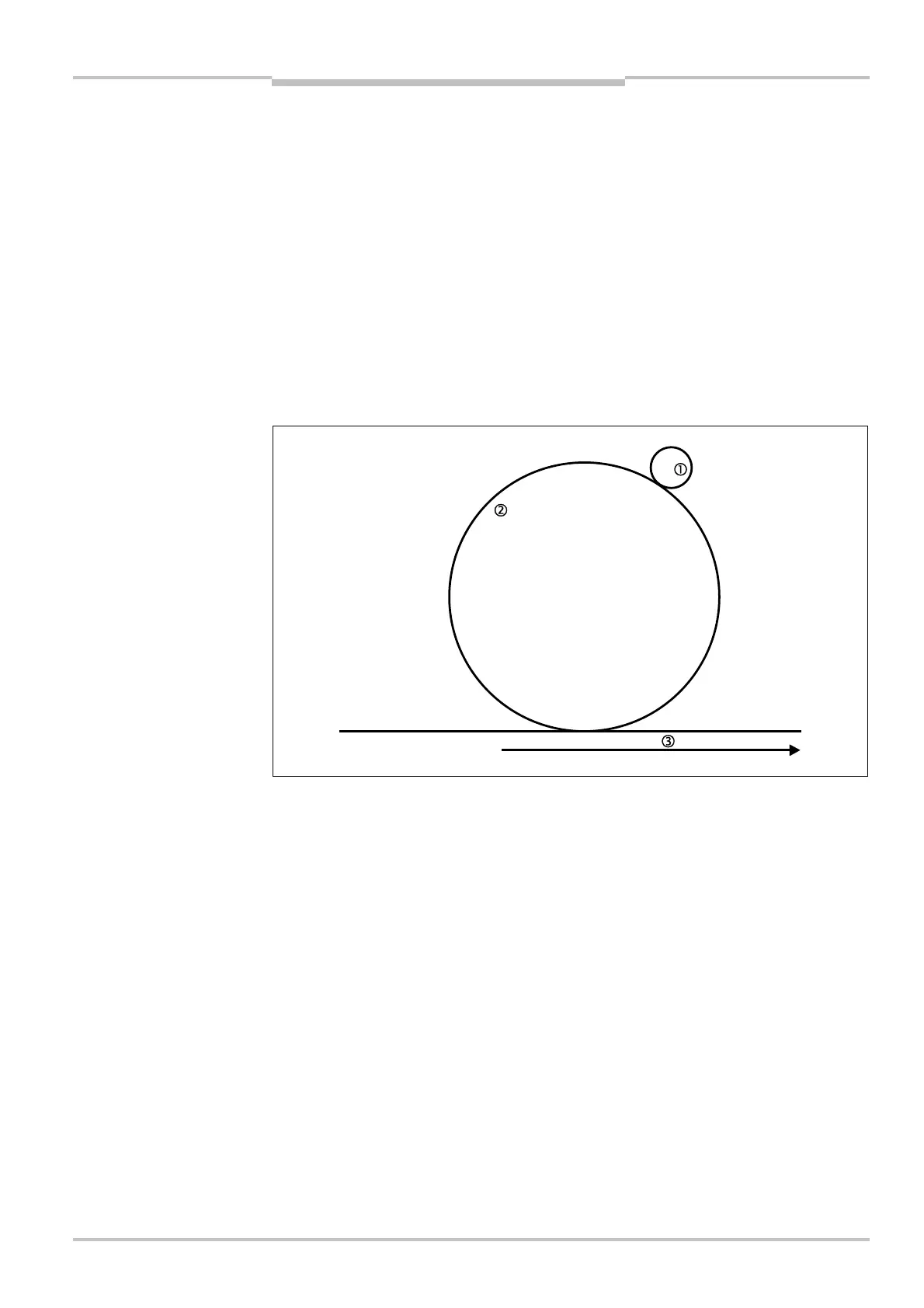
per cm travel
Friction wheel 3.5 cm
Forklift truck wheel
35 cm
Distance covered by the
AGV