Chapter 11 Operating instructions
S300
110 © SICK AG • Industrial Safety Systems • Germany • All rights reserved 8010948/YY96/2016-02-17
Subject to change without notice
Diagnostics
11.4 Error and status indications on the 7@segment display
T
his section explains the meaning of the error indications on the 7<segment display and
how to respond to the messages. You will find a description of the positions and symbols
on the S300 in section 3.4 “Status indicators” on page 24.
The lock-out operational status
I
n case of certain faults or an erroneous configuration, the device can go into the lock-out
operational status. To place the device back in operation, proceed as follows:
Rectify the cause of the fault as per Tab. 33.
Switch off the power supply for the S300, wait at least 3 seconds and then switch back
on the power supply.
Or:
Restart the safety laser scanner with the aid of the CDS.
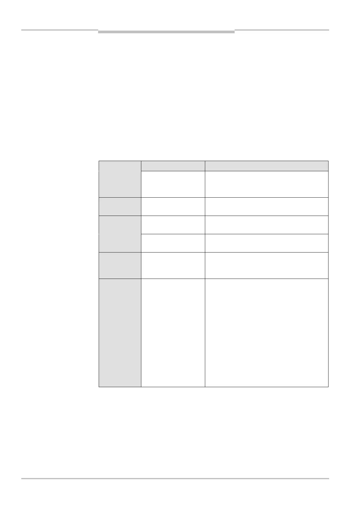
Display Possible cause Rectification of the error
, , , ,
, , ,
Power-up cycle — all
segments are acti-
vated sequentially.
No error
Object in protective
field
No error
Object in warning
field 1
No error
Object in warning
field 2
No error
Object in protective
field
(in compatibility mode)
No error
Initialization of the
device
or
Waiting for the end of
the initialization of a
second device connec-
ted to the EFI
The display goes out automatically when the
S300 has been initialized and/or the
connection to the second device has been
made.
If the display does not go off:
Check whether the partner device is in
operation.
Check the wiring.
If no partner device is connected:
Check the system configuration with the aid
of the CDS. Transfer the corrected
configuration to the S300 again.
indications on the 76segment
display