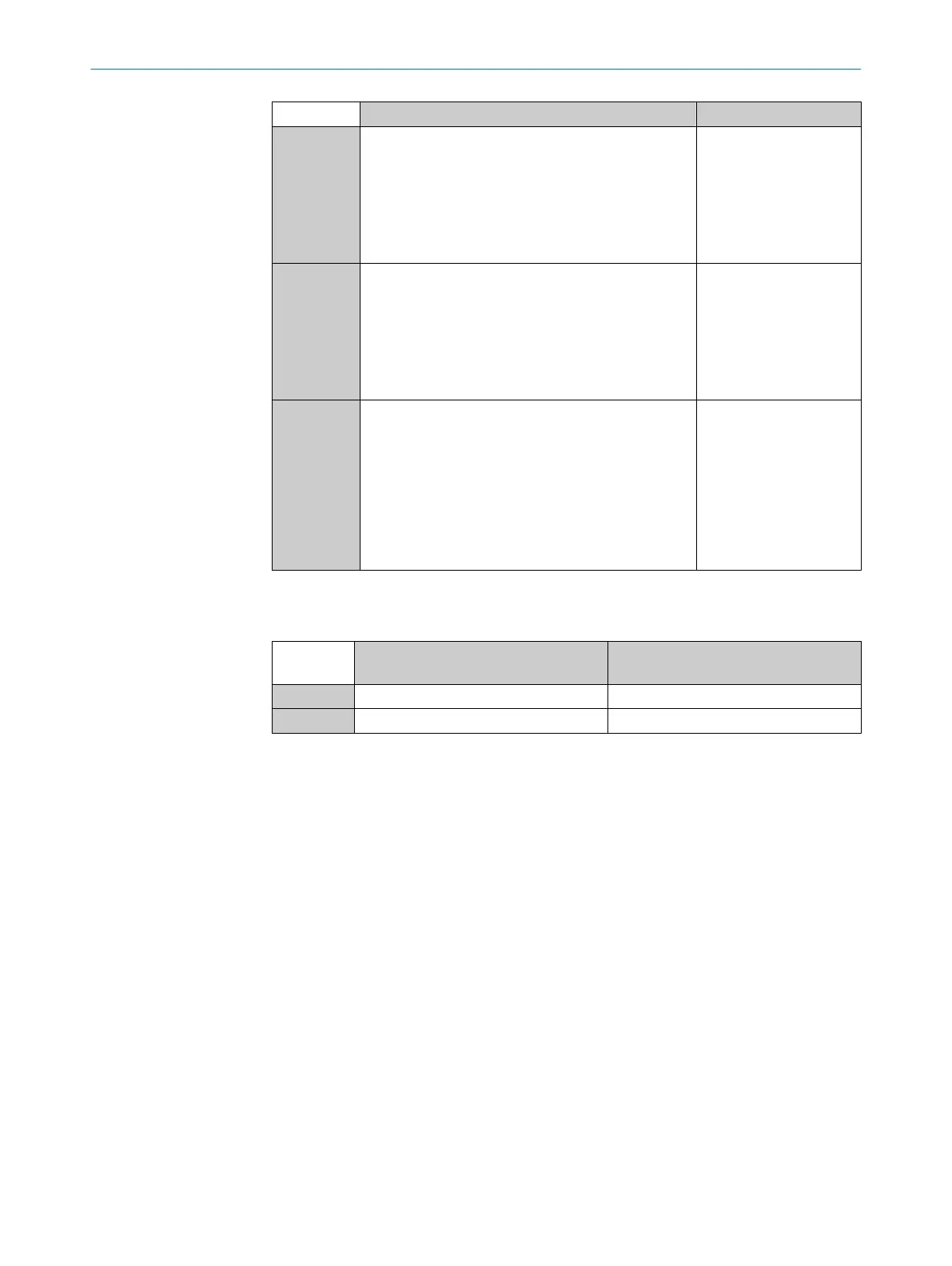
Position 12 Inputs and outputs, data interface Connection type
G
•
3 x switching output (Q) and
•
1 x analog output (QA)
or
•
1 × input (IN) and
•
2 × switching output (Q) and
•
1 x analog output (QA)
M12, 8-pin, A-coded
I
•
2 × switching output (Q) and
•
1 x RS-485 interface
or
•
1 × input (IN) and
•
1 x switching output (Q) and
•
1 x RS-485 interface
M12, 8-pin, A-coded
R
•
4 x switching output (Q)
or
•
1 × input
•
3 x switching output (Q)
or
•
2 x inputs
•
2 × switching output (Q) and
M12, 8-pin, A-coded
3.2.3 Optical properties
Table 6: Sensing range and minimum detectable object length
Position
14 and 15
Sensing range Minimum detectable object length
00 Special Special
05 2.5 m 4 mm
3.3 Structure and function
The MLG-2 is an optical automation light grid. It comprises a sender and a receiver.
The sender consists of sender optics, several sender elements (LEDs), and actuation
electronics. The receiver consists of receiver optics, several receiver elements (photodi‐
odes) and actuation electronics.
3 PRODUCT DESCRIPTION
14
O P E R A T I N G I N S T R U C T I O N | MLG-2 WebChecker 8024643/2019-09-02 | SICK
Subject to change without notice