3.3.1 Device components
M12; 5pol
M12; 4pol
M12; 8pol
rs
4
Teach
Alignment
link/data
RS485
5
7
8
6
9
1 2
3ß
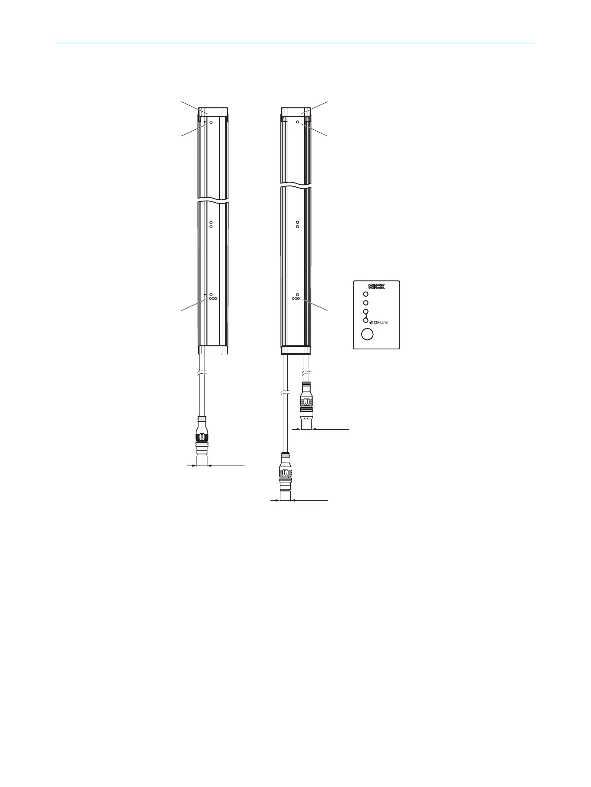
Figure 4: Device components
1
Sender
2
Receiver
3
Receiver LED
4
LED display
5
Control panel at the rear of the receiver
6
Ethernet connection for configuration via TCP/IP
7
Receiver connection: Voltage supply, inputs, outputs and synchronization
8
Sender connection: Voltage supply, synchronization and test input
9
LED display
ß
Sender LED
3.3.2 Measurement principle
Providing no object is located between the sender and receiver, the light beams from
the sender LEDs will hit the receiver LEDs.
If an object is located between the sender and receiver, the light beams will be inter‐
rupted, depending on the size of the object.
PRODUCT DESCRIPTION 3
8024643/2019-09-02 | SICK O P E R A T I N G I N S T R U C T I O N | MLG-2 WebChecker
15
Subject to change without notice