3. Insert the sender and receiver into the brackets.
4. Align the sender and receiver with each other.
5. Clean the position of the sender and receiver.
5.3.2 Mounting the FlexFix bracket
CAUTION
Protruding screws!
Protruding screws could cause injuries.
b
Select the length of the M5 screws so that no injuries from protruding screw parts
are possible.
CAUTION
Possible machine damage!
Excessive tightening torques may damage the bracket. If the tightening torques are too
low, the mounting of the MLG-2 is not secured.
b
Comply with the specified tightening torques.
In the FlexFix bracket, the sender and receiver can be flexibly rotated by ±15°.
Mounting variations
•
Mounting on the side
•
Mounting on the back
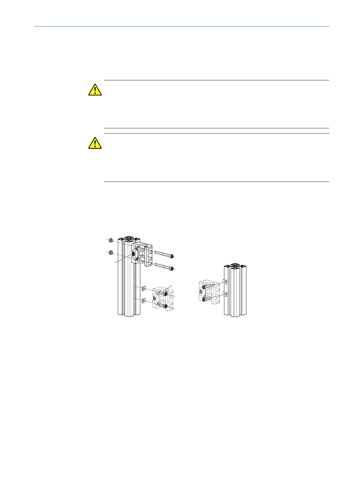
Figure 28: Mounting the FlexFix bracket
1
Side mounting (2 variants)
2
Mounting on the back
3
M5 screw
4
Screw for fastening
The M5 screws are used to mount to the machine or profile frame through the bracket.
A nut or threaded hole is required on the machine or profile frame.
Select an M5 screw of sufficient length for the bracket and machine and profile frame.
Required number of brackets depending on the device length:
•
MLG-2 ≤ 2 m: 2 senders, 2 receivers
•
MLG-2 > 2 m: 3 senders, 3 receivers
Mounting Flex-FIx bracket and sender and receiver
1. Mount brackets for the sender. Screw tightening torque: 5 to 6 Nm. All brackets
must be in alignment to be able to turn the sender.
5 MOUNTING
36
O P E R A T I N G I N S T R U C T I O N | MLG-2 WebChecker 8024643/2019-09-02 | SICK
Subject to change without notice