10.4.6 “Analog output” menu
The “Analog output” menu is only displayed if the MLG-2 variant is equipped with ana‐
log outputs.
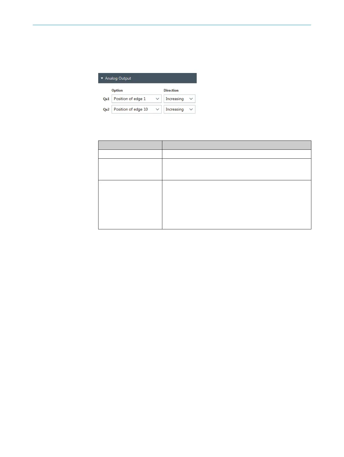
You can parameterize the function for the analog outputs via the “Analog output” menu.
Figure 65: “Enhanced Sensing” page, “Analog output” menu
Table 31: Analog output
Designation Description
Qa1, Qa2 Designation of the analog output
Option Select edge or function for which the analog output is to be out‐
put.
Option: Edge 1 to edge 10 or function 1 to 10
Direction Assignment of the 4 mA value and the 20 mA value.
•
Rising: The 4 mA value corresponds to the lower measurement
field limit. The 20 mA value corresponds to the upper measure‐
ment field limit.
•
Falling: The 4 mA value corresponds to the upper measure‐
ment field limit. The 20 mA value corresponds to the lower
measurement field limit.
Parameterizing analog outputs example
1. Select the desired option for the analog output.
2. Select the assignment of the 4 mA and 20 mA value for the “Direction” parameter.
Example
•
Measuring range: 0 to 240 mm
•
Selection option for analog output Qa1: Edge 1 position
•
“Direction” parameter: Rising
°
4 mA correspond to 0 mm
°
20 mA correspond to 240 mm
•
60 mm is measured for edge 1.
Result: 8 mA are output at analog output Qa1.
You can parameterize the measuring range using the "Blanking” menu. see "“Blanking”
menu", page 67
10.4.7 “Digital configuration” menu
You can parameterize the functions for switching outputs and switching inputs using the
“Digital configuration” menu.
CONFIGURATION WITH SOPAS 10
8024643/2019-09-02 | SICK O P E R A T I N G I N S T R U C T I O N | MLG-2 WebChecker
75
Subject to change without notice