CAUTION
Possible machine damage!
Excessive tightening torques may damage the bracket. If the tightening torques are too
low, the mounting of the MLG-2 is not secured.
b
Comply with the specified tightening torques.
The two mounting surfaces for the brackets of the sender and receiver must not be
angled more than ± 2° to each other. If not possible, use the optional FlexFix bracket.
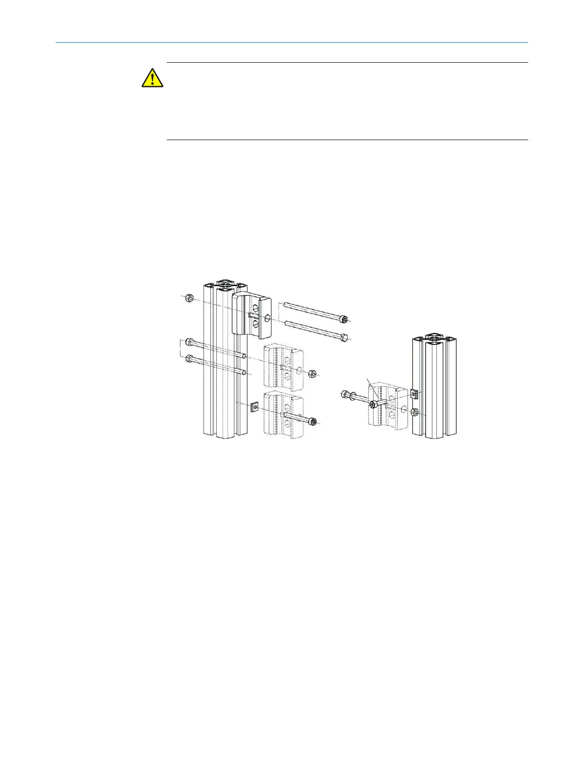
The QuickFix bracket consists of two parts, which are pushed into each other. The two
individual parts are connected using an M5 screw, and the sender or receiver is
clamped with form-fit clamping.
Mounting variations
•
Mounting on the side
•
Mounting on the back
Figure 27: Mounting the QuickFix bracket
1
Side mounting (3 variants)
2
Mounting on the back
3
M5 screw for lateral mounting
4
M5 screw for rear mounting
Variants for side mounting with machine or profile frame
•
Fasten the M5 screw to the machine or profile frame through the QuickFix bracket.
A nut or threaded hole is required on the machine or profile frame.
•
Fasten the M5 screw to the QuickFix bracket through the machine or profile frame.
A nut is required for each QuickFix bracket.
Select an M5 screw of sufficient length for the bracket and machine and profile frame.
For rear mounting, select the length of the M5 screws so it is possible to clamp the
sender and the receiver in the bracket.
Required number of brackets depending on the device length:
•
MLG-2 ≤ 2 m: 2 senders, 2 receivers
•
MLG-2 > 2 m: 3 senders, 3 receivers
Mounting Flex-FIx bracket and sender and receiver
1. Mount brackets for the sender. Screw tightening torque: 5 to 6 Nm.
2. Mount brackets for the receiver. Screw tightening torque: 5 to 6 Nm.
MOUNTING 5
8024643/2019-09-02 | SICK O P E R A T I N G I N S T R U C T I O N | MLG-2 WebChecker
35
Subject to change without notice