12 RS-485
You can configure the output of process data via the RS-485 interface using SOPAS ET.
The transmission message comprises the following parts:
•
A frame
This can be configured.
•
The application data
20 slots are available and can be individually filled with all types of data from the
MLG-2. The sequence of the data to be transmitted is determined by the configu‐
ration of the corresponding slots.
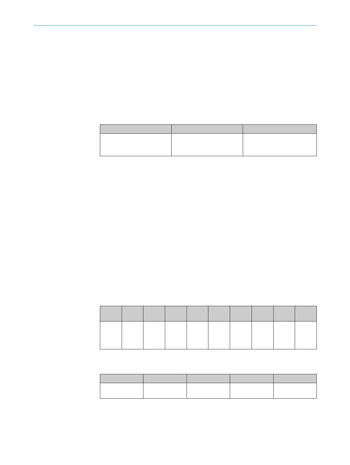
Table 35: User-defined data output
Frame start Application data Frame end
e.g. STX Slot 1 to 20
1
Consists of up to
2 stop characters, e.g. CR LF
(default = ETX and None)
1
Depending on the configuration, the individual slots can be separated using separators.
The start and stop characters can be configured. Separators can be configured
between the application data slots see ""RS-485” menu", page 77.
12.1 Application data
You can configure diagnostic data and measurement data as application data.
Diagnostic data
•
System status
•
Statuses of the switching outputs
•
Quality of teach
•
Process quality (quality of run)
•
Flow counter
Measurement data
•
Edge 1 position to edge 10 position
•
Function 1 to function 10
System status
Table 36: Content of the system status
Bit 9 ...
15
Bit 8 Bit 7 Bit 6 Bit 5 Bit 4 Bit 3 Bit 2 Bit 1 Bit 0
Reserve
d
Sensor
teach-in
suc‐
cessful
Syn‐
chro‐
nization
error
Teach-
in error
Hard‐
ware
error
QoR
alarm
Teach-
in
active
Excess
temper‐
ature
warning
Process
data
invalid
Output
short-
circuit
Statuses of the switching outputs
Table 37: Content of the switching output statuses
Bit 4 ... 15 Bit 3 Bit 2 Bit 1 Bit 0
Q5 ... Q16 (vir‐
tual)
Q4 Q3 Q2 Q1
12 RS-485
80
O P E R A T I N G I N S T R U C T I O N | MLG-2 WebChecker 8024643/2019-09-02 | SICK
Subject to change without notice