4.5 Required minimum distances for several objects
You must comply with the following minimum distances for several objects:
•
Measurement field border - edge
•
Edge - edge
rs
3
1
2
B
B
B
4
13,5
A A A
A
62
5
6 7
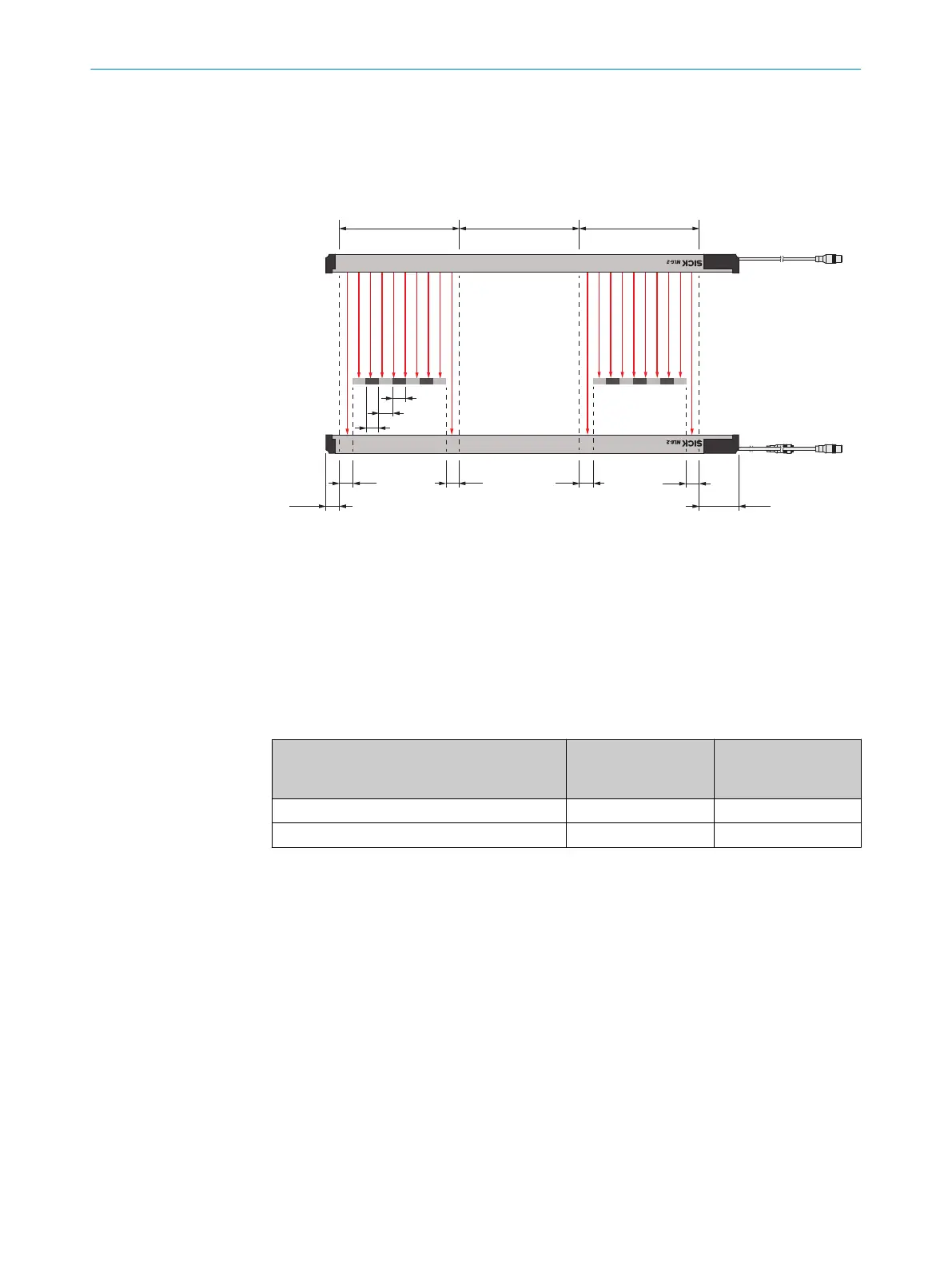
Figure 19: Edge measurement distances
1
Head side measurement modules
2
Empty modules
3
Connection side measurement modules
4
B: Necessary distance between edge - edge
5
A: Necessary distance between measurement field border - edge
6
Head side blind zone
7
Connection side blind zone
Table 11: Required distances A and B
Description Distance A (measure‐
ment field border -
edge)
Distance B (edge -
edge)
Typical distance 23 mm 25 mm
Minimum distance under ideal conditions
1
8 mm 10 mm
1
Ideal conditions: Homogeneous material, optimal ambient conditions and optimal object position
4.6 Minimum and maximum object width
The minimum and maximum object width is dependent on the number and the compo‐
sition of the measurement modules and the empty modules.
The maximum object width is calculated as follows. There must not be an empty mod‐
ule on the head side or the connection side.
•
Maximum object width = (number of measurement modules + number of empty
modules) x 150 mm – 2 x distance A
Example 1: Maximum width with empty modules
•
Maximum number of measurement modules: 16
•
Maximum number of empty modules: 5
•
Typical required distance A: 23 mm
•
Maximum object width = (16 + 5) x 150 mm – 2 x 23 mm = 3,104 mm
4 PLANNING
26
O P E R A T I N G I N S T R U C T I O N | MLG-2 WebChecker 8024643/2019-09-02 | SICK
Subject to change without notice